Keywords: communication; MIG; arc; control
0 Preface
The AC MIG welding process has been proposed for a long time and there is some research work. The more recent research work is the double concave welding current control scheme. The main problem solved is the alternating magnetic arc to overcome the magnetic bias of the DC arc [1][2].
There has been a lot of research work on arc physics, droplet transfer characteristics and welding process characteristics of MIG welding with direct current and positive wire (DCEP). There are also some research work on arc physics, droplet transfer characteristics and welding process characteristics of DC and DCEN MIG welding [3].
The DCEP pulse MIG (PMIG) arc is stable, the arc force is favorable for the droplet transfer, the arc penetration force is strong, the weld penetration is large, and the molten pool collapse phenomenon is likely to occur when the thin plate is welded. DCEN MIG welding, because the welding wire is the cathode, the cathode spot jumps up and down at the wire end, the arc stability is not good, the arc force is not conducive to the droplet transfer, the weld penetration is shallow, and it is easy to produce welding defects such as poor fusion, convex weld bead, etc. [3].
The AC pulsed argon arc welding (AC PMIG) arc consists of EP polarity and EN polarity and can be viewed as alternating switching between DCEP PMIG arc and DCEN MIG arc. Reasonable use of DCEP PMIG and DCEN MIG arc advantages, design AC PMIG welding arc control mode to ensure the stability of the welding arc and the stability of the droplet transfer process to ensure the stability of the welding process. Switching AC PMIG welding composed of DCEP PMIG and DCEN MIG, the characteristics of arc force and arc heat should be between DCEP PMIG and DCEN MIG, and the weld penetration should be between the two, the largest weld fusion Deep is the weld penetration of DCEP PMIG, so this welding process will facilitate the welding of thin sheets.
With the development of the times, in order to reduce the weight of products, thin plates, especially aluminum alloy sheets, have been widely used, and many thin plates require arc welding in the manufacturing process. The most common quality problem when soldering a thin plate is the collapse of the molten pool. To this end, it is necessary to study the welding process with shallow welding pool and fast welding speed to stabilize the welding quality and improve the welding efficiency.
In addition, when the thin plate is welded, the welding current is small, the arc stiffness is weak, and the arc is easily affected by the arc magnetic biasing. The AC PMIG alternating current arc can overcome the magnetic bias of the direct current arc, which is beneficial to stabilize the welding process and the welding quality.
1 AC PMIG welding current waveform control mode
Fig. 1 is a diagram showing an arc current waveform control mode when AC PMIG is normally welded. The AC PMIG AC arc consists of EP polarity and EN polarity. The EP polar arc facilitates the droplet transfer, and the EN polar arc is not conducive to the droplet transfer, so the droplet transition process is designed during the arc EP polarity time. Droplet transition is the best form of droplet transfer, which is achieved with arc EP polarity pulse current control in order to achieve this form of droplet transfer under a wider weld specification. There is only one pulse current in an EP polarity time, which controls the pulse current Ip and the pulse time Tp to achieve a pulse transition of one droplet. In an AC cycle time TC, except for the pulse time Tp, the rest time is the base time (including the EP polarity base time Tb1, Tb2, EN polarity time TEN. As shown in the figure, the current in the base time The values ​​Ib1, Ib2, and IEN are small, at least not able to produce droplet transfer. Figure 1 shows that the AC PMIG pulse frequency is consistent with the AC frequency, also known as the AC pulse frequency, and the droplet transfer control is one pulse per week.
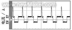
Figure 1 AC PMIG welding current waveform control mode
AC PMIG welding arc welding power supply with dual inverter arc welding power supply, controlled by 80C196KC.
2 AC PMIG welding arc behavior and droplet transfer
The welding experiment was carried out using an independently developed AC PMIG welding equipment. Figure 2 is an arc current waveform when AC PMIG is welded to an aluminum alloy. In the welding experiment, the workpiece material LF6 was welded with Φ1.2 mm Al-Si5 aluminum alloy welding wire, the flow rate of argon gas was 9 l/min, and the welding speed was 0.380 m/min.
Corresponding to the AC PMIG welding process of Figure 2, high-speed imaging is performed with an imaging speed of 3000 frames per second. Analyze high-speed camera images to study AC PMIG welding arc behavior and droplet transfer characteristics.

1-Ia 140 A/div, 2-Ua 32 V/div, t 50 ms/div
Figure 2 Welding current and voltage waveform of AC PMIG welded aluminum alloy
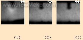
Figure 3 AC PMIG welding arc shape high-speed camera picture
Fig. 3(3) is a picture of the arc shape when the arc EP polarity pulse current, the arc brightness is obviously enhanced to present a bell-shaped bright area, and the arc highlight area has a clear boundary line. This is consistent with the arc pattern at the pulse current of the DCEP PMIG welding.
Compared with DCEP PMIG welding, AC PMIG welding changes the EN polarity arc during an AC pulse period, which is beneficial to reduce the arc plasma flow force and the arc's force on the weld pool.
Figure 4 is a high-speed image of an AC PMIG welding arc in an EN polarity time, showing the change in liquid metal at the wire end during EN polarity. AC PMIG welding arc EN polarity time, the welding wire is the cathode of the arc, the cathode pressure drop is larger than the anode pressure drop, the cathode heat generation is greater than the anode heat generation, although the arc current is small (47 A), the cathode heat generation promotes the welding wire Melting. With the continuation of the base time, the liquid metal generated by the melting of the wire gathers at the wire end, and the diameter of the liquid metal at the wire end increases, as shown in Fig. 4 (1) to (9), which shows the melting of the wire by the arc EN base current. effect. Secondly, during the polar period of the arc EN, the liquid metal formed by melting has a phenomenon of swaying from side to side, as shown in Figures 4(1) to (9). The welding experiment shows that the formation of an appropriate amount of liquid metal during the arc EN polarity time and the occurrence of a small swing phenomenon do not affect the normal welding process.
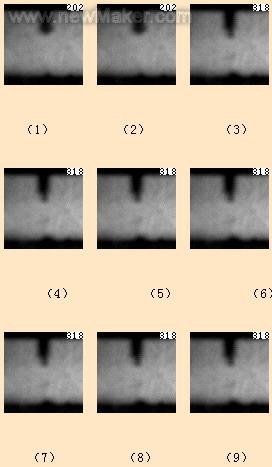
Figure 4 High-speed camera picture of AC PMIG welding arc EN polarity
Due to the current value when controlling the proper EN polarity, no droplet transition occurs during the EN polarity, which is the intention of the designed AC PMIG welding control mode. If the control is not proper, the melt transition occurs when the EN polarity, which will lead to instability of the welding process.
Figure 5 is a series of 18 high-speed camera images of AC PMIG welding arc. It mainly shows the arc shape and droplet transfer characteristics of EP polarity pulse current. During the arc EP polarity base current, the welding wire is the anode, and the anode heat generation is small, so there is no change in the diameter of the wire end during this time, which is basically maintained; the welding wire is the anode, and the arc is evenly distributed at the lower end of the welding wire. The liquid metal at the wire end is subjected to a uniform force, and the liquid metal has no tendency to sway to the left and right, as shown in Figs. 5(1) to (7). During the arc EP polarity pulse current, as the pulse current rises, the temperature and ionization degree of the arc column area increases, the brightness of the arc column area increases, and a bright area appears, as shown in Fig. 5(8)~(15). The arcing area is below the wire end and covers the lower half of the wire tip droplet. The arc-brightening zone is essentially composed of a metal vapor plasma where the current density is high and the temperature is high. As the pulse current rises and the pulse time increases, the arc highlight area expands, and the arc highlight area always maintains the bell shape during the arc expansion. At the falling edge of the pulse current, a droplet transition phenomenon occurs, as shown in Figures 5(13)-(15). As the droplets leave the wire end, the arc length increases and the arc jumps below the new wire end, as shown in Figure 5 (14). As the pulse current decreases, the arc highlight area decreases; at the end of the pulse current, the arc highlight area disappears. Entering the base current time, the arc shape is shown in Figure 5 (15) ~ (18), and the arc bright area below the wire end is in a thin bundle.
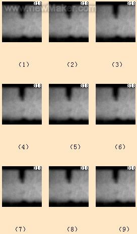
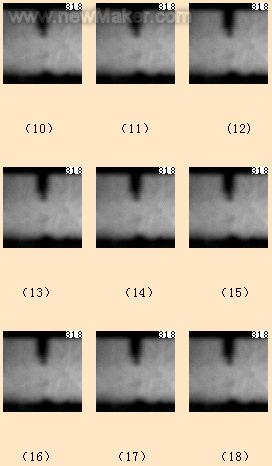
Figure 5 Continuous high-speed camera picture of AC PMIG welding
3 weld forming of AC PMIG welding
The welding test was carried out with the self-developed AC PMIG welding equipment. The influence of the EN ratio of the AC PMIG welding parameters on the weld formation was mainly studied. Welding test wire material Al-Si5, diameter φ1.2 mm; welding workpiece thickness 3 mm, material LF6; argon flow rate 9.5 l / min. At the wire feeding speed of 4.33 m/min and the welding speed of 0.58 m/min, the weld forming of AC PMIG welding EN ratio equal to 0 (ie DCEP PMIG welding) is shown in Fig. 6(1); AC PMIG welding EN ratio The weld bead formed at 40% is shown in Fig. 6(2). The weld penetration of the latter is significantly reduced compared to the former. Weld forming shows that under the conditions of constant wire feeding speed and welding speed, the weld penetration of AC PMIG welding is shallower than that of DCEP PMIG welding. Increasing the EN ratio will reduce the weld penetration.

(1) EN%=0(2)EN%=40
Figure 6 Photograph of weld formation of AC PMIG welding
(1) When the AC PMIG welding arc EN polarity, the wire end is surrounded by the cathode spot, the arc jumps around the wire end, and the smaller base current has a melting effect on the wire. Control the appropriate EN polarity current and time, no droplet transfer, and the welding process is stable.
(2) During the AC PMIG welding arc EP polarity pulse current, the arc presents a typical bell-shaped bright region, which controls the appropriate pulse current and pulse time, and can realize a stable droplet transfer process with one pulse and one drop.
(3) Under the conditions of constant wire feeding speed and welding speed, when AC PMIG is welded with aluminum alloy, the weld penetration decreases as the EN ratio increases.
Wall Lamp,Solar Wall Lights,Garden Wall Lights,Outdoor Wall Lantern
NINGBO ZHENGUO INTELLINGENT LIGHTING CO.,LTD , https://www.nbzguolight.com