In the manufacture of molds, the use of text is more common, you can use special software to make embossing or intaglio where needed. In addition to using some professional engraving software, this kind of work can be done easily with EdgeCAM.
First, the placement of text
EdgeCAM has a special text function. In use, we complete the text placement in design mode. The command for the text function is: Modeling → Text. After using the command, the "Create Text Features" dialog box shown in Figure 1 pops up. Here you can see that EdgeCAM provides two kinds of text, namely vector text and TrueType text. You can choose one of them during use.
For both types of text, you can mirror, height, size, auto-adjust, rotate, adjust position, and more. In Fig. 1, the mirror image refers to the horizontal and vertical mapping along the position of the key point of the text to form a mirror image; the height refers to the size of the input text; the vertical refers to the direction of the text; the automatic adjustment refers to the rectangle according to the input. Adjust the position of the text; rotation refers to the angle of the text centered on the key point; adjustment refers to placing the key point at the left, middle or right position of the text as needed; the name refers to the given text as needed The name can also be given.
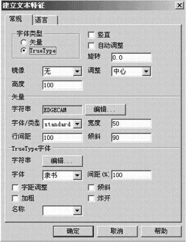
Figure 1 Create a text feature dialog
Vector text, according to a given string, gets a line of text, and its text can only be letters and numbers. In processing and use, it is generally used for intaglio of numbers and letters.
TureType font, according to the given string, is the wireframe text, when the text is used, the font that comes with the computer system is called. Therefore, it is possible to satisfy the need by adding various fonts to the computer. In use, various adjustment functions, such as distance between text, bold, and tilt, are similar to the operation commands of Word software. When popped up, the string can be broken into line segments. However, after the blast, it is not allowed to edit and modify it again in text mode. When using it, it is generally recommended not to blast it. If the line segment method is needed, an offset can be obtained.
Once you have determined the text, you can type the text in the window. When inputting, if automatic adjustment is selected, the rectangle formed by two points is used to determine the key point of the text. Otherwise, the mouse input is the key position.
In addition, when using, you can also input the text by reading the two-dimensional text in AutoCAD, thus eliminating the process of creating a text model.
Second, the text adjustment
In actual use, it is often necessary to adjust the size, shape and position of the text. Sometimes it may be necessary to do some circularly distributed text, then you need to use some specific features of EdgeCAM to adjust the text features.
First, in terms of text changes and adjustments, EdgeCAM provides a text feature dialog, as shown in Figure 2. Just double-click the text you want to edit to get the text feature dialog for the corresponding text. The content of the dialog box is basically the same as the content of the text dialog box. It is used to adjust various parameters of the text according to actual needs. If you need to transfer the position of the text, you can use coordinate input or automatic adjustment to adjust. Among the display options, there are line styles, colors, and layers for adjusting text.
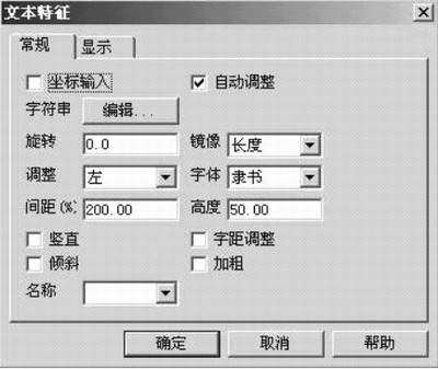
Figure 2 text feature dialog
Similarly, with the movement, rotation, scale, and offset commands given by the software, we can also modify the position, angle, size, and thickness of the text.
It is worth noting that when doing circular arc-arranged text, for vector text, we can get the position corresponding to the text by rotating (with copy), and then modify it to get the required arrangement text; but for TureType font, because The text of the font has a corresponding key point value, so when the text is modified after the rotation, the text position returns to the original position. In this regard, when we adjust, we can modify the text first, and then rotate the text (with copy). Then modify and then rotate (with copy) on the original text, which requires several words and several times of the above operations can be completed. Of course, we can also arrange the text by first setting the position and then giving the text.
For example, we can give a point, then rotate the point (with copy) to get a series of neatly arranged points, then we use these points as the key points of the input text to input the text, and finally adjust the string of the text. And the angle, you can get the corresponding style. Although this method requires a certain process when inputting, it can obtain some characters with different shapes.
With the offset of the text, you can get some bold or thin text. When the command meets the text, it will automatically cut off the intersection of the intersecting texts to obtain the shape of the style shown in Figure 3. This method can be used when the style is needed, but if you need the full text, you can blow it up when you type the text.

Figure 3 text layout effect
Third, the processing of text
After the text is placed, switch the mode to the machining mode and start machining. There are many ways and means for text processing. Here are a few examples.
1. Use text milling function
Text milling is the easiest way to process text, but it is limited to vector text and can only be used for intaglio. Since it is a line type text, the size of the text is determined by the size of the tool radius.
After specifying the tool, select Milling → Text Milling and the “Text Engraving†dialog box shown in Figure 4 will pop up. In the general options, specify the feed rate, the number of reductions, the spindle speed, and the tolerance value during machining. Given the name of the machining; in the cutting depth option, the approximate plane, the retraction position, The reference plane, the depth of cut, and the position at which the tool is placed after cutting. After filling in the parameters, specify the vector text to be processed to form the tool path.
Among these parameters, you can find that this type of text engraving can only give a depth of cut, indicating that only text of the same depth can be engraved. At the same time, since the vector text cannot be input into Chinese, the limitations in use are great.
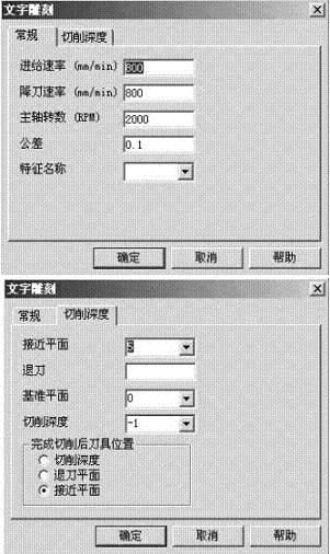
Figure 4 text engraving dialog
2. Processing of TureType fonts by 2D outer contour milling, roughing, etc.
In EdgeCAM, the general TureType font uses 2D outer contour milling or roughing to achieve Chinese text milling.
With 2D contour milling, the contour shape of the text is formed, which is similar to the function of text milling. After selecting the 2D contour milling command, you will get the contour milling dialog shown in Figure 5. The option settings are basically the same as those for other milling contours. It should be noted that in the advanced option, the engraving item is selected, so that it automatically cancels the contour parameter and obtains the actual machining method that is the engraving parameter.
During machining, depending on the options in the contour selection, you can adjust whether the path taken by the tool during contour milling is along the inside or outside of the text. Cavity machining requires the location of the cavity within the specified profile.
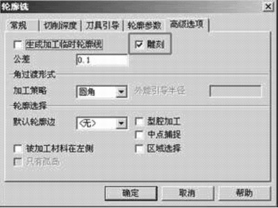
Figure 5 Contour milling dialog
This kind of processing can solve the milling of the outline of the text, but it can not form the intaglio in the true sense, nor can it form the required embossing. So in practice, we are more about roughing.
Roughing can be achieved in both intaglio and embossing. In use, the wire frame method is used for processing, and after the processing parameters are set, the text to be processed is selected, and the corresponding intaglio pattern can be obtained. When embossing is required, the text and the outer frame to be cut are selected at the same time. At this time, the computer will filter through the processing area - non-processing area - processing area to complete the processing style.
3. Using equal roughness processing
In the above processing methods, since they are all carried out by wireframe method, the depth of the text can only be controlled uniformly by setting the depth of cut during use. For curved surfaces or solid models, it cannot be obtained. Convex and indentation of the surface equivalent. When such engraving is required, we can achieve this by using equal roughness processing.
After the text is adjusted, select the roughness command to get the dialog box of Figure 6. Since we are processing the text using equal roughness command processing, there will be some changes in the parameter selection. First of all, in the machining allowance, this parameter will become the engraving depth or convex height of the text. In use, the absolute value of this margin is required to be smaller than the radius of the tool. Given the negative value, the selected cutting surface can be obtained.
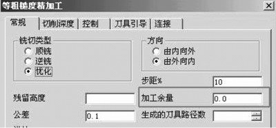
Figure 6 General tabs for roughness processing
In the option of cutting depth, the parameter of the value does not change, and the cutting depth will determine the lowest position of the tool during machining, as shown in Figure 7.
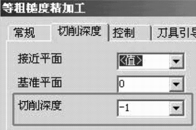
Figure 7: Depth of Cut tab in Roughness Machining
Several of the following tool guidance options and connection options are important when used for text processing. Among them, in the tool guiding option, since it is based on the principle of ensuring the entire area in the equal roughness processing, the part outside the area is used for guiding the tool during machining. When we use it to process text, the area of ​​the text will be used as the processing area, and the tool guiding part is not allowed, so in Figure 8, the type option is none. Similarly, we set the import length of the tool to 0, so as to ensure the integrity of the text boundary, as shown in Figure 8. In the connection options, there is a short connection distance which is the most important setting item. The meaning is that in the area, when the distance between the tool paths is smaller than this value, a short connection can be made. Since the text often has a small gap when it is used, if the connection is made, the text may be destroyed. Therefore, when using the text, it is recommended to set the value to 0, as shown in Figure 9.
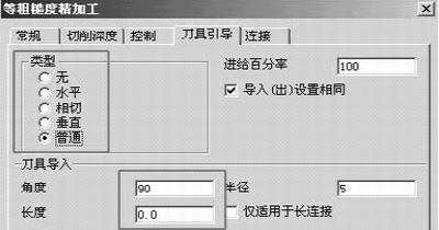
Figure 8 Tool Guide tab in Roughness Machining

Figure 9 Connection tab in roughness processing
The setting of the option is completed and it is necessary to return to the selection part of the machining. First choose the face to be processed. Once a face is given, it is required to select the element that retains the boundary. Here, if the intaglio is made, the text is given; if the embossing is done, the text and the outer boundary are given (given the position to be cut). Finally, the concave and convex embossing on the surface can be completed by giving other parameters as required.
Fourth, the conclusion
In practical applications, it may be necessary to adjust the radius compensation or offset according to the actual situation in order to obtain a complete text. Of course, when using, we can also use roughing, contour milling or other methods to achieve text processing. EdgeCAM offers a wide variety of machining commands that can be selected to suit your needs. In use, which processing command is not fixed, any method is feasible as long as it meets the requirements.
The structure of the core barrel is generally divided into single - acting double core tube and most of the fishing apparatus. The double tube section consists of an outer tube assembly and an inner tube assembly. The outer pipe assembly includes; The main structure and working principle of the cartridge stopper, cartridge chamber, stable joint outer pipe, diamond reamer and diamond bit are as follows:
(1) Spear structure is composed of spear head and recovery spring. When coring, the fishing device is lowered to the upper part of the inner tube assembly in the drill pipe, and the fishing hook grasps the fishing spear, lifts the fishing device up, picks up the recycling card barrel, and inwardly compressing the cartridge card, so that the inner tube assembly and the outer tube are separated, so that the inner tube assembly is lifted up.
(2) The clip structure is mainly composed of the clip frame, clip, spring and other components. Its function is that when the inner tube sits on the outer tube, the clip expands with the help of the elastic force of the expansion spring and sticks to the inner wall of the clip chamber, so that the drilling tool can achieve positioning.
(3) Buffer structure by spring, locking mother, split pin composition. Protecting the inner tube when pulling the core.
(4) Single action structure is realized by two pairs of thrust bearings.
(5) Adjust the length of the inner pipe assembly and the outer pipe assembly of the structure, and fine-tune the lower shaft and the locking mother to achieve the gap required by the end of the spring seat and the step inside the drill bit.
(6) The fishing structure, also known as the fishing device, is mainly composed of fishing hook, hammer and safety rope. The fishing hook is used to hold the spearhead while fishing the inner pipe, and the weight is used to speed up the fishing device's descent to save fishing time. The safety rope is a thin rope. When the inner pipe is stuck for some reason and cannot be lifted, the safety rope can be forcefully lifted and then the drill can be lifted.
Other Parts,Spearhead Base,Compression Spin,Core Lifter
wuxi shengmeirun trading co.,ltd. , https://www.wxsmrxz.com