Abstract: In order to realize the self-developed CAD/CAM software for impeller NC machining, an interference test and a tool position correction algorithm are proposed. The interference is divided into three types by analyzing the relative positional relationship between the tool and the impeller surface. Corresponding inspection and correction methods are proposed for different types of interference. Finally, a simulation example is given to verify the effectiveness of the algorithm.
The impeller is a key component of turbomachinery, and its numerical control machining has always been the focus of research. Since there is no mature and adaptable CAD/CAM system in China, most manufacturers of impellers rely on software imported from abroad to complete their multi-axis CNC machining. Imported software is not only expensive, but also costs a lot of foreign exchange, and the software is a closed operation module. The technical difficulties of some difficult problems and some key problems are difficult to obtain. Therefore, it cannot be modified and developed according to actual conditions, which seriously hinders the new products. Developed.
In recent years, with the rapid development of machinery and aerospace industry, the requirements for improving the processing quality and precision of impeller parts are becoming more and more urgent. It is imperative to develop independent CAD/CAM software. For this reason, many researchers have carried out this aspect. Research work, but there is little information on the research on the key issue of interference inspection in CNC machining. Wu Ming’s doctoral dissertation “Engineering Design and Numerical Control Machining of Impellers and Blade Parts†of Beijing University of Aeronautics and Astronautics uses discrete triangles to perform interference analysis. The calculation is large and the research is not comprehensive. The interference between them was not analyzed. In the NC machining process of the integral impeller, the working space of the tool is strictly limited by the structure of the impeller, and the interference phenomenon is much more complicated than the machining of the free surface. Based on the characteristics of the overall impeller, based on the analysis of the interference type, this paper proposes a set of interference checking methods suitable for multi-coordinate NC machining.
The integral impeller means that the hub and the vane are on a blank substrate. When machining the impeller blade surface, in addition to the interference between the tool and the blade being machined, the tool is easily interfered with the adjacent blade due to the small space between adjacent blades. In actual machining, the blade surface is given by means of coordinate points. When calculating the tool position, the surface needs to be discretized. Since the ball-end tapered milling cutter is generally used, the curved surface can be separated into a dot column. The information of each point will be given in the form of structure, including the sequence number of the arrangement, the coordinates of the point, the unit surface normal of the point, and the points are given in the form of a single necklace.
The interference discussed in this paper refers to the tangent interference, that is, the part of the tool that should be retained on the curved surface. In machining a blade with a milling cutter, the orientation of the tool placed on the tangent plane of the curved surface at the point of contact is taken as the initial position of the tool. Figure 1 shows the case where the milling cutter processes the integral impeller. From the perspective of the relative positional relationship between the tool and the blade surface, the interference can be divided into three types: the first is the interference between the milling cutter and the blade tip of the blade: the second is the milling cutter and the adjacent blade. Interference between the tips of the leaves: The third is the interference between the milling cutter and the adjacent points around the area being machined. If these three types of interference checks are passed, it is not necessary to perform interference verification on the points of the entire blade surface, thereby greatly reducing the amount of calculation.
1 Introduction
The impeller is a key component of turbomachinery, and its numerical control machining has always been the focus of research. Since there is no mature and adaptable CAD/CAM system in China, most manufacturers of impellers rely on software imported from abroad to complete their multi-axis CNC machining. Imported software is not only expensive, but also costs a lot of foreign exchange, and the software is a closed operation module. The technical difficulties of some difficult problems and some key problems are difficult to obtain. Therefore, it cannot be modified and developed according to actual conditions, which seriously hinders the new products. Developed.
In recent years, with the rapid development of machinery and aerospace industry, the requirements for improving the processing quality and precision of impeller parts are becoming more and more urgent. It is imperative to develop independent CAD/CAM software. For this reason, many researchers have carried out this aspect. Research work, but there is little information on the research on the key issue of interference inspection in CNC machining. Wu Ming’s doctoral dissertation “Engineering Design and Numerical Control Machining of Impellers and Blade Parts†of Beijing University of Aeronautics and Astronautics uses discrete triangles to perform interference analysis. The calculation is large and the research is not comprehensive. The interference between them was not analyzed. In the NC machining process of the integral impeller, the working space of the tool is strictly limited by the structure of the impeller, and the interference phenomenon is much more complicated than the machining of the free surface. Based on the characteristics of the overall impeller, based on the analysis of the interference type, this paper proposes a set of interference checking methods suitable for multi-coordinate NC machining.
 1. Hub 2. Blade 3. Tool Figure 1 Overall impeller machining |
2 interference type
The integral impeller means that the hub and the vane are on a blank substrate. When machining the impeller blade surface, in addition to the interference between the tool and the blade being machined, the tool is easily interfered with the adjacent blade due to the small space between adjacent blades. In actual machining, the blade surface is given by means of coordinate points. When calculating the tool position, the surface needs to be discretized. Since the ball-end tapered milling cutter is generally used, the curved surface can be separated into a dot column. The information of each point will be given in the form of structure, including the sequence number of the arrangement, the coordinates of the point, the unit surface normal of the point, and the points are given in the form of a single necklace.
The interference discussed in this paper refers to the tangent interference, that is, the part of the tool that should be retained on the curved surface. In machining a blade with a milling cutter, the orientation of the tool placed on the tangent plane of the curved surface at the point of contact is taken as the initial position of the tool. Figure 1 shows the case where the milling cutter processes the integral impeller. From the perspective of the relative positional relationship between the tool and the blade surface, the interference can be divided into three types: the first is the interference between the milling cutter and the blade tip of the blade: the second is the milling cutter and the adjacent blade. Interference between the tips of the leaves: The third is the interference between the milling cutter and the adjacent points around the area being machined. If these three types of interference checks are passed, it is not necessary to perform interference verification on the points of the entire blade surface, thereby greatly reducing the amount of calculation.
3 interference check and tool position adjustment
- Interference between the tool and the tip of the blade
- The effective radius of the tool is
Where: r0 is the tool ball nose radius: b is the tool's half cone angle: cos q = AB•a/|AB|.R 0 = r 0 + |AB|cos q tan b (2) - The judgment of the type of interference between the cutter and the adjacent blade tip is similar to the judgment of the first interference. The parametric curve of the adjacent blade tip can be obtained by rotating the tip parameter point of the blade to a clockwise or counterclockwise rotation angle a ( a = 360 m, m is the number of blades).

Figure 2 The third type of interference detection - Interference between the tool and the adjacent points around the area being machined
- Then the equation of plane F 1 is
Ax+ By+ Cz= 1 (4) - The directional distance d from any point (xs, ys, zs) on the blade surface to the tangent plane can be obtained by equation (5)
d= Ax s + By s + Cz s - 1 (5) 
Figure 3 Interference coarse judgment
The sign of d can be obtained by calculating equation (5). If d is the same number and greater than zero, no interference occurs: if d is an alien sign, interference occurs, and d<0 is the interference point.
In order to further reduce the amount of calculation, coarse judgment is performed before the above calculation is performed. The purpose of the rough judgment is to find the coverage area between the blade surface and the tool. Interference can occur in the coverage area. Since the first type of interference check has been passed, we further reduce the coverage area during the calculation.
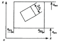
Project the tool and the surface of the blade being machined onto the xoz plane. The inclusive square of the tool is constructed with the diameter of the ball head as the side length, and the tolerance rectangle of the blade surface is constructed by the maximum and minimum x values ​​and z values ​​of the blade surface, as shown in Fig. 3. By observing the relative positional relationship between the square and the rectangle, it can be determined whether the points on the blade surface require further inspection.- Tool position adjustment The interference is checked by the above method, and the tool axis must be adjusted. The third interference is eliminated below. According to formula (5), the maximum interference distance can be found as
Max|d|= max|Ax s + By s + Cz s - 1| (6) 
Figure 4 Example of interference simulation
To eliminate interference, the tool should be rotated by an angle of q around the center of the tool in the initial tangent plane, causing the tool axis to deviate further from the surface of the blade being machined. q angle is
Where d 1 is the distance between the maximum interference point and the center point of the tool.q = arcsin(max|d|/d 1 ) (7) - The adjusted tool axis vector is
a new = a cos q ± n sin q (8)
In the above formula, if the q angle is rotated ( a × n ), the clockwise rotation takes the "+" sign, and the counterclockwise rotation takes the "-" sign.
The first type of interference is the same as the third type of interference adjustment method, and the cutter axis should be more deviated from the curved surface. For the second type of interference, the cutter axis should be close to the curved surface. After the tool axis angle is adjusted, re-examine the interference until no interference occurs.
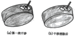
The interference check method proposed above has been used in the "dedicated impeller CAD/CAM software" system developed by us. Figure 4 is two simulation examples. The tool position in Figure 4a is calculated from the tool position and the dark color indicates the interference area. Figure 4b shows the location of the tool after the interference is removed using the above algorithm. - The directional distance d from any point (xs, ys, zs) on the blade surface to the tangent plane can be obtained by equation (5)
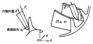
The impeller surface is discretized by NURBS method and can be represented by S(u,v)={x(u,v),y(u,v),z(u,v)}, u∈(0,1),v∈ (0,1). Therefore, this type of interference only needs to determine the distance e between the points on the parameter line corresponding to the v=0 of the blade surface tip to the tool axis, as shown in Fig. 2. If the distance is greater than the effective radius of the tool, no interference occurs: if the distance is less than the effective radius of the tool, interference occurs. The so-called effective radius of the tool refers to the radius of the tool relative to the tip of the blade. Distance e is
| (1) |
In theory, this type of interference should detect the existence of the intersection of the conical surface of the tool and the surface in the area covered by the tool, but the calculation is more complicated and the calculation amount is larger. For the sake of simplicity, the following algorithm is employed.
As shown in Fig. 2, the cutting plane of the tool is made such that the angle of intersection with the tool axis vector is the tool half cone angle, and two tangent planes F 1 and F 2 are obtained , and a plane F in contact with the blade surface is selected. 1. Find the directional distance d between the plane and the discrete points covered by the tool. Determine the sign of d to determine whether the tool interferes with the blade surface.
The unit normal vector n 1 (A, B, C) of the plane F 1 can be obtained by rotating the tool axis vector a around ( a × n ) (90° -b ), ie
| n 1 = cos(90°- b ) a + sin(90°- b ) n | (3) |
Electric Grinder Tool,Bodum Burr Grinder,Electric Angle Grinder,Electric Burr Grinder
Ningbo Hoya Electronic Commerce Co., LTD , https://www.jauhitools.com