Combining some design software for application is an effective way to solve engineering problems. This article illustrates how to combine AutoCAD and SolidEdge for application, aiming to provide a reference for engineers and technicians.
AutoCAD, a software developed by Autodesk, has been widely used in manufacturing since its inception, with its powerful 2D drawing and editing capabilities. This is why it has long appeared on designer computers; however, its 3D modeling capabilities. And related editing tools are far less than other 3D design software, such as SolidEdge of US UGS Company, Solidworks of Solidworks, etc. With these 3D CAD design software, we can easily design and construct 3D solids, and can easily carry out physical design. Update, quickly generate basic engineering views; although you can edit and modify 2D drawings in SolidEdge, users who are used to drawing graphics with AutoCAD always feel that AutoCAD is not easy to operate. If we can use AutoCAD and SolidEdge ingeniously together, it will make the design and manufacture of the product easier. This article will use examples to illustrate how to combine AutoCAD and SolidEdge for application.
The legend in this paper is the axial view of the machine shown in Figure 1. The dimensions are shown below.
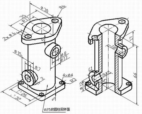
Figure 1 Axle and dimension identification of the machine
If you use AutoCAD to draw the axonometric drawing in the axonometric mode directly, the biggest difficulty is the drawing of the intersecting line when the cylinder intersects the cylinder. Because the intersecting line is neither a circle nor an ellipse, use the circle command. Drawing an arc command or drawing an ellipse command cannot be accurately drawn. It must be approximated by a spline curve by making an auxiliary line, a special point and a general point. In addition, because the size of each part is relatively cumbersome, the time taken to draw such an isometric drawing will be much longer than the time to construct the 3D model of the part. In fact, the original impulse of a person when designing a part is three-dimensional, a three-dimensional entity with associated concepts such as color, material, hardness, shape, size, position, and related part manufacturing process. Therefore, we may wish to start with the three-dimensional model of the machine. In AutoCAD, although 3D model design can also be carried out, due to its data structure and technical reasons, the design update and modification are quite difficult, so you can consider using SolidEdge into 3D modeling.
First, create a three-dimensional model
Open the SolidEdge cascading menu, as shown in Figure 2, click on "Solid Parts" to enter the part design module. In the part design interface, the three-dimensional model design of the machine is completed by using the commands of stretching, material removal, digging and chamfering, and is saved as shown in Fig. 3. In order to obtain the axial sectional view of the mechanism, a cutting entity must be created, and the front right portion of the mechanism is removed by using the cutout command on the basis of the previous entity, as shown in FIG. 4, and saved. Close the file.
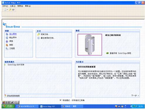
Figure 2 Open SolidEdge into the cascading menu
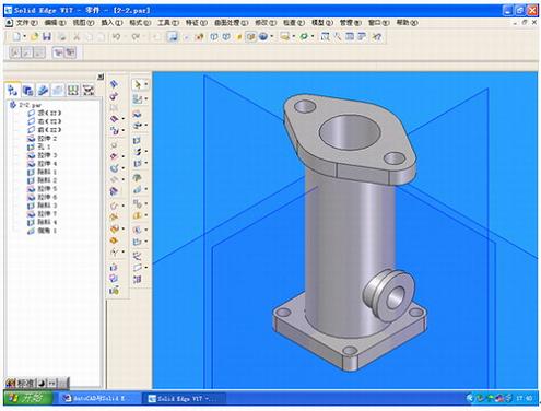
Figure 3 Creating a 3D solid in the SolidEdge part design module
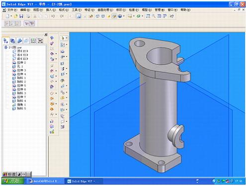
Figure 4 Creating a cut model of the entity
Second, create a drawing
Click "Project" in the SolidEdge cascading menu to enter the drawing generation module. Use the "Drawing View Wizard" command to open the part document of the machine just created and select it in the "Named View" list. "Axis map", close the "drawing view wizard" dialog box, set the scale to 1:1 on the toolbar, and use the mouse to give the position of the isometric map on the drawing interface, as shown in Figure 5. Using the "Main View" command, pull out the axonometric view of our desired orientation based on the axonometric map, as shown in Figure 6. The three-dimensional model part file of the machine is also arranged in the same way in the drawing, and the unnecessary view is deleted, as shown in FIG. 7 . The next step is to edit the graphics and dimension. Although the size of the isometric drawing can be marked in the SolidEdge drawing module, it is more troublesome to adjust. Especially when you are unfamiliar with SolidEdge's annotation format setting and editing, you can't do it. . At this time, we may wish to use AutoCAD to complete the simple work of graphic editing and dimensioning.
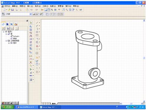
Figure 5 Generating an isometric drawing in the SolidEdge drawing generation module

Figure 6 generates an isometric view in the other direction
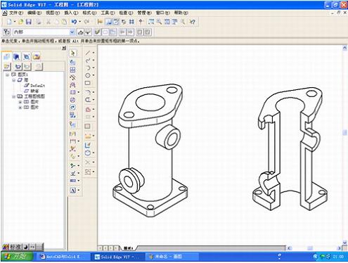
Figure 7 Adding the isometric view of the cut model
Third, save as AutoCAD document
Under the File menu, click Save As to open the Save As dialog box, as shown in Figure 8. In "Save as type", select "AutoCAD document (*dwg)", give the file name in the file name, and click "Save". This is a key step in converting a SolidEdge drawing document to an AutoCAD document, so that the saved document can be opened in AutoCAD.
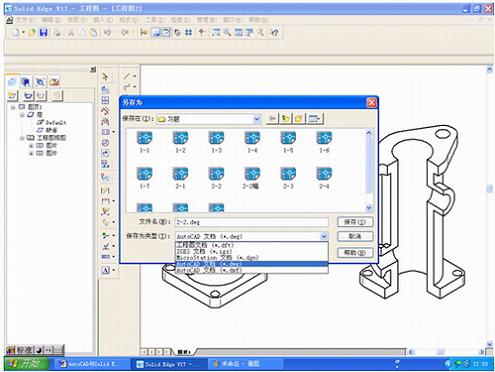
Figure 8 Save the generated graphics in the SolidEdge drawing generation module as AutoCAD documents.
Fourth, open the drawing created by SolidEdge in AutoCAD
Open AutoCAD, enter the drawing interface of AutoCAD, click "Open" under the "File" menu, enter the "Select File" dialog box, select the file you just saved, click "Open", you can open the axis of the machine in the drawing area Mapping. After adjusting its display, as shown in Figure 9. At this time, the isometric drawing can not be edited and labeled, because each graphic corresponds to a tile. To edit, you must use the “decompose†command to decompose the graphic before editing and labeling. After decomposition, all the line types of the graph are thin solid lines. Use the Layer Property Manager to set the line width of the isometric drawing so that the outline of the isometric drawing is displayed in thick solid lines. At this time, the axial expansion coefficient of the isometric drawing is not 1, because the axial mapping generated in the SolidEdge drawing generation module is generated according to the formation projection of the isometric drawing, and the axial expansion coefficient is about 0.82. In order to dimension and view the size, it is easy to draw the axial expansion coefficient when the drawing is normal. Therefore, before the dimensioning, the axial expansion coefficient of the graphic should be changed to 1 by the “zoom†command.
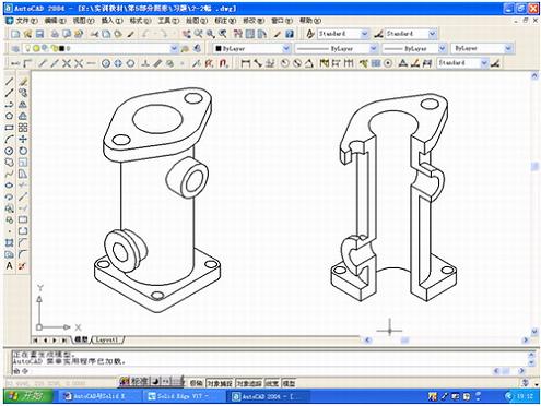
Figure 9 The generated graphics in the SolidEdge drawing generation module are opened in AutoCAD.
Five, dimensioning in AutoCAD
In the AutoCAD format menu, set the "text style" and "label style", and set the corresponding layer, you can do the dimensioning, the specific steps are not described, as shown in Figure 10.
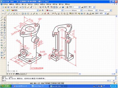
Figure 10 Labeling with AutoCAD's text and dimensioning features
Conclusion
As an engineering technician, in the actual work, faced with a large number of application software, we can not all be very skilled in application, may be more skilled in the common functions of some of the more commonly used software, for some not Commonly used features and some settings may not be familiar. Therefore, in the work, we should be good at combining different kinds of software for application, taking advantage of each other, avoiding shortcomings, improving our work efficiency, and making the work easier and faster. Applying AutoCAD to SolidEdge is an effective way to solve some engineering problems.
Our automatic door kits include 1 motor+gear reducer, 1 belt,7 meter, 1 idle pulley, Microprocessor, 4 sets of carriage blue wheels, 2 sets of floor guides,2pcs remote control, 2 sets belt clamp mounting brackets, 1 power supply harness and cable connectors, 2 locator, Aluminum track whose length is 2.08 meter, 3 meter, or 4 meter.
We are a manufacturer of automatic door openers that are designed to provide people convenience. Automatic Door Systems` drive to provide that level of service is but one of the reasons why automatic doors are becoming more and more popular. Our Automatic Sliding Door systems are modern, space-saving and elegant.
Automatic sliding doors have many basic functions some of which include: automatic mode with full opening width and/or reduced opening width, and exit only for traffic control. The opening of automatic doors can also be adjustable to make the opening width smaller or larger. Important safety functions such as safety sensors prevent the door from shutting if persons or objects are in the detection zone. If the door leaves are inhibited when closing, they are immediately re-opened or if the door leaves are hindered when opening, they are immediately stopped by a safety automatic reversing mechanism.
Our most popular sliding automatic door. Think of this as the go-to door for everyday automation needs. All components fully tested and pre-assembled at factory for fast, trouble-free installation.
Applications: Retail, healthcare, airports, hospitality, clean rooms. Shenzhen Hongfa Automatic Door Co.,Ltd rated door is designed, test and certified to meet your environment needs. automatic slide doors for industrial, commercial, healthcare, and retail use. You will find our automatic sliding doors throughout in a wide variety of locations, including: Hospitals, Airports, Retail centers, Pharmacies, Hotels, Grocery stores, Hardware stores, Sporting goods stores, and more.
Automatic Sliding Doors can either be a single door sliding in one direction or bi-parting doors where each door leaf slides in the opposite direction. They are often used in grocery stores, entrances to shopping malls, hospitals and other applications where you want to provide your customers a hands free, safe and easy access to your building.In addition, one of the biggest benefits of automatic doors is energy savings. Since these doors only open when someone comes in or out of your building, it prevents the loss of energy when a door may otherwise be left open for a long time.
The control device of sliding automatic door contains basic function and extensional function, automatic operation / hold-open/closed/half-open to meet customer needs. Electric sliding door controller has multiple interfaces for complete access control systems for keeping your life and property more safety. Such as: safety beam photocell, electric locks, sensor etc. Its drive devices adopts European technology to integrate motor with gear box, which offers strong driving and reliable operation and increased power output , it can adapt to a large door.
Providing strength, beauty, and technology all in one package, Hongfa's line of automatic sliding doors provides entrance solutions for practically any application. An exclusive feature is Hongfa's sound-dampening track reducing operational noise to a mere whisper and stops vibration resonance that can be transferred to the building structures.
Automatic Door Kits,Automatic Sliding Door Opener,Automatic Sliding Door Operator,High Performance Automatic Door Kits
Shenzhen Hongfa Automatic Door Co., Ltd. , https://www.hffreezerdoor.com