Superhard material tools have an exclusive advantage in the field of high-speed cutting, and their practical applications are increasing. Among these tools, PCD (polycrystalline diamond) tools are the best choice for high-speed cutting of aluminum alloys and non-metallic materials, while diamond-coated tools have not only been put into practical use and the growth momentum is very strong; PCBN (cubic boron nitride polycrystalline) Products) Tools are suitable for cutting cast iron, hardened steel and other materials at higher speeds. CBN (cubic boron nitride) coated tools are also expected to achieve major technological breakthroughs in the near future.
In order to achieve a high service life and low cutting force for high speed cutters, the optimum tool geometry should be selected for different workpiece materials. Compared with ordinary cutting, the front angle of high-speed cutting tools is generally smaller or even negative front angle, the rear angle is slightly larger, and the rounding or chamfering tool tip is often used to increase the rake angle to prevent the cutting edge. Thermal wear. Since the rotary cutter for high-speed cutting is required to work at a high rotational speed, the centrifugal force problem is very prominent, so the structure of the cutter body and the blade clamping structure are required to be very reliable, and at the same time, it is required to undergo strict dynamic balance on the dynamic balancer, It can be further installed on the machine to balance the movement with the spindle assembly.
The 7:24 cone coupling widely used between the tool and the spindle at normal speed. When rotating at high speed, the solid taper shank cannot be “expanded†by the centrifugal force like the spindle hole. The gap between the two will cause the tool to The inside of the cone is oscillated, causing axial positioning errors of the tool and breaking the dynamic balance of the structure. In order to overcome the shortcomings of such high speed performance, some coupling methods suitable for high speed cutting have been developed, such as HSK tool system and Capto tool system.
The selection of the tool, tool holder and cutting amount is detailed below.
1 tool material
Tool material is key to achieving high speed cutting. High-speed cutting materials mainly include cemented carbide, coated tools, cermets, ceramics, cubic boron nitride and diamond tools. They each have advantages and are suitable for different workpiece materials and different cutting speed ranges. It must be noted that there is an adaptability problem between the tool material and the workpiece material pair, that is, the performance of one tool material and the workpiece material is good, but it is not ideal when processing another workpiece material. In other words, there is no one. The universal tool material is suitable for high speed machining of all workpiece materials.
High-speed cutting tool materials must be selected based on the workpiece material being processed and the processing properties. In general, ceramic tools, coated tools and CBN tools are suitable for high-speed machining of ferrous metals such as steel; PCD tools are suitable for high-speed machining of non-ferrous metals such as aluminum, magnesium and copper. The table lists some of the workpiece materials that are suitable for machining the above tool materials.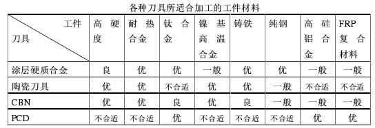 Ceramic tools have been used to process a variety of cast iron, steel, thermal spray welding materials, nickel-based superalloys.
Diamond tools are suitable for processing non-metallic materials, non-ferrous metals and their alloys. Due to the poor thermal stability of diamond, the hardness is lost when the cutting temperature reaches 800 °C. Because diamond and iron have strong chemical affinity, iron atoms easily interact with carbon atoms at high temperatures to convert them into graphite structures, and the tools are easily damaged. Therefore, diamond tools are not suitable for processing steel materials, when cutting non-ferrous metals. The life of PCD tools is tens or even hundreds of times that of cemented carbide tools.
Cubic boron carbide tools are suitable for roughing and finishing of hardened steel, bearing steel, high speed steel and chilled cast iron, and are also suitable for high speed cutting of high temperature alloys, thermal spray materials, hard alloys and other difficult materials. The CBN tool is one of the best tools for car grinding.
2 cutter
The following describes the common tools for machining housings on machining centers.
1, milling cutter
In face milling, size and position are important factors due to the relationship between the milling cutter and the workpiece. When selecting a tool, the width of the workpiece determines the diameter of the milling cutter. For small machining parts, the general tool diameter is 30% larger than the workpiece, but machine power and stability play a decisive role in many cases. Face milling often takes several passes to complete.
The blade of the milling cutter is another important factor in optimizing the milling results. It is an advantage to have more than one blade to be cut at the same time in any one milling, but too many blades participating in the cutting are disadvantages. It is impossible for each cutting edge to cut at the same time during cutting, and the required power is related to the number of cutting edges participating in the cutting. The position of the milling cutter relative to the workpiece plays an important role in the chip formation process, the cutting edge load and the machining results. In face milling, with a milling cutter that is approximately 30% larger than the cutting width and positions the milling cutter close to the center of the workpiece, the chip thickness does not change much. The chip thickness cut in and out is slightly thinner than the cutting thickness at the center cutting.
In order to ensure that a sufficiently high average chip thickness per tooth feed is used, the number of cutter teeth suitable for this process must be correctly determined. The pitch of the milling cutter is the distance between the effective cutting edges. According to this value, the milling cutter can be divided into three types - a fine-tooth milling cutter, a sparse-tooth milling cutter, and a special-tooth milling cutter.
Also related to the chip thickness of the milling is the leading angle of the face milling cutter. The lead angle is the angle between the main cutting edge of the insert and the surface of the workpiece, with a 45 degree, 90 degree angle and a circular insert. The change of the cutting force direction will change greatly with the difference of the main declination: the milling cutter with the main declination of 90 degrees mainly produces radial force, which acts in the feed direction, which means that the surface to be machined will not be subjected to More pressure is more reliable for workpieces with weaker milling structures.
The milling cutter with a main angle of 45 degrees has roughly the same radial cutting force and axial direction, so the pressure generated is relatively balanced and the machine power requirements are relatively low. It is especially suitable for milling short-cut materials that produce chipping chips. Workpiece.
A circular blade milling cutter means that the main deflection angle varies continuously from 0 to 90 degrees, depending on the depth of cut. This blade has a very high cutting edge strength and is suitable for large feed rates due to the relatively thin chips generated along the long cutting edge. The direction of the cutting force along the radial direction of the insert is constantly changing and the pressure generated during machining will depend on the depth of cut. The development of the geometric geometry of the modern blade makes the circular blade have the advantages of smooth cutting effect, low power requirement for the machine tool and good stability. Today, it is no longer an effective roughing cutter, and it has a wide range of applications in face milling and end milling.
There are two ways to feed the workpiece and the direction of rotation of the milling cutter. The first is down-cutting. The direction of rotation of the milling cutter is the same as the direction of feed of the cutting. At the beginning of the cutting, the milling cutter bites the workpiece and cuts the last chip. The second type is up-cut milling. The direction of rotation of the milling cutter is opposite to the direction of feed of the cutting. The milling cutter must slide over the workpiece before starting the cutting. The cutting thickness starts at zero and the cutting thickness reaches the end of the cutting. maximum.
When three-sided milling cutters, some end milling or face milling, the cutting forces have different directions. In face milling, the milling cutter is just outside the workpiece, and the direction of the cutting force should be especially noted. When milling, the cutting force presses the workpiece against the table, and the cutting force causes the workpiece to leave the table during up-cut milling.
Since the cutting effect of the down-milling is the best, the down-cutting is usually preferred. Only when the machine has a thread gap problem or if there is a problem that cannot be solved by the down-milling, the up-cutting is considered.
Ideally, the cutter diameter should be larger than the width of the workpiece, and the cutter axis should always be slightly off the workpiece centerline. When the tool is placed against the center of the cutting, burrs are easily generated. The direction of the radial cutting force as the cutting edge enters the cutting and exits the cutting will continue to change. The machine tool spindle may vibrate and be damaged, the blade may break and the machined surface will be rough. The milling cutter is slightly off center and the cutting force direction will no longer fluctuate - the milling cutter will get a preload. We can drive the center milling to the center of the road.
Each time the milling insert enters the cutting, the cutting edge is subjected to an impact load, which depends on the cross-section of the chip, the material of the workpiece and the type of cutting. It is an important direction for proper bite between the cutting edge and the workpiece when cutting in and out.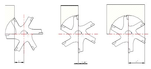 In Figure a, the cutter axis is completely outside the width of the workpiece and the impact force at the time of the cut is received by the outermost tip of the blade, which means that the initial impact load is absorbed by the most sensitive part of the tool. Finally, the milling cutter also leaves the workpiece with the tip of the tool, that is to say, the cutting edge is cut from the beginning to the cutting edge, and the cutting force acts on the outermost cutting edge until the impact force is unloaded. In Figure b, the center line of the milling cutter is just on the edge line of the workpiece. When the chip thickness reaches the maximum, the blade is out of the cutting, and the impact load is maximized when cutting in and out. In Fig. c, the axis of the milling cutter is located within the width of the workpiece. The initial impact load when cutting is carried along the cutting edge from the farthest point of the most sensitive tool tip, and the blade exits the cutting smoothly when the blade is retracted.
For each blade, the way the cutting edge leaves the workpiece when exiting the cutting is important. The material remaining near the retraction may reduce the blade clearance somewhat. When the chips are detached from the workpiece, an instantaneous tensile force is generated along the rake face of the blade and burrs are often generated on the workpiece. This tensile force jeopardizes the safety of the cutting edge in hazardous situations.
When the milling cutter axis and the workpiece edge line coincide or approach the edge line of the workpiece (Figure b), the situation will be severe. A summary of achieving better milling:
1 Check the power and stiffness of the machine to ensure that the required cutter diameter can be used on the machine.
2 The overhang of the tool on the spindle is as short as possible. Influence of the axis of the milling cutter and the position of the workpiece on the impact load
3 Use the correct milling pitch suitable for the process to ensure that there are not too many blades at the same time to engage the workpiece to cause vibration during cutting. On the other hand, ensure that there are enough blades and when milling narrow workpieces or milling cavities. The workpiece is engaged.
4 Ensure that the feed per blade is used to achieve the correct cutting results when the chips are thick enough to reduce tool wear. The indexable insert with positive rake groove shape provides smooth cutting results and lowest power.
5 Select the diameter of the milling cutter suitable for the width of the workpiece.
6 Select the correct lead angle.
7 Place the milling cutter correctly.
8 Use cutting fluid only when necessary.
9 Follow the rules for tool maintenance and repair and monitor tool wear.
2, drill bit
The drill bit is the most widely used tool in hole machining tools. Especially when drilling holes below Ñ„30mm, the drill bit is structurally divided into integral and indexable insert drill bits. Due to the pursuit of high production efficiency in the automotive industry, more and more The application of shoulder and chamfer composite drills is also becoming more widespread.
Many workpieces require drilling a hole or holes, and today most of these holes are machined on CNC machines and machining centers. In principle, there are many different types of holes, and the most common difference between these holes is the fit clearance. These holes include threaded holes, holes that are well matched to the requirements, pipe holes, and holes that are machined to remove weight. These holes are through holes or blind holes and have different requirements for cutting tools and methods.
In the drilling process, in order to achieve a satisfactory effect in an effective manner, four main factors need to be considered.
1 ratio of diameter to hole depth
2 precision and surface roughness required for the machined hole
3 workpiece material type, quality and hardness
4 machine tools, especially machining conditions and spindle speed
These factors will influence the choice and application of the drill bit type. The stability of workpieces, machine tools and process systems is paramount in all processes. The drilling process plays a role in determining what type of drill is suitable for the machining process. The smallest indexable insert has a diameter of 12.7 mm.
3, sickle
The boring tool is divided into an integral type, a clamping type and an adjustable type according to the structure, and the adjustable type is further divided into a fine adjustment type and a differential type. Commonly used in the processing of automotive transmission housings are single-edged fine-tuning boring tools and double-edged rough boring tools.
The rough boring tool uses an axial adjustment mechanism to make the heights of the two blades completely uniform, achieving an ideal balance and preventing vibration. The feed screw is the lifeblood of the fine boring head. In some manufacturers, the paired production method is adopted to minimize the backlash between the screw and the nut to obtain the highest reliability. In the hole on the back side, it is often necessary to reverse the workpiece or turn the table. This is not only a waste of time, but also it is difficult to ensure the coaxiality. The EWN fine boring head produced by BIG in Japan only needs to reverse the blade. Perform ruthenium processing to ensure accuracy and improve production efficiency. For the hole with high precision requirements, the arbor has high dynamic balance effect. In the high-speed small hole fine boring head moving balance ring produced by BIG, the built-in balance block will move, and the balance ring will be rotated according to the relevant data in the manual. To the corresponding position, the hoe can be balanced.
4, tapping
There are two kinds of tapping methods on the machining center, high-precision automatic reverse thread tapping machine, the maximum speed is 6000r/min, and the rigid tapping without any compensation is needed. These two kinds of tapping methods have their own advantages and disadvantages, so they are selected according to the processing requirements. In the mass production, due to the pursuit of high efficiency, the automatic reverse thread tapping device will be beneficial to production, but its mechanism is complex, the accessories are numerous, and the maintenance is not easy. expensive. At present, with the increase in the number of CNC machining centers, rigid tapping will become increasingly popular.
When rigid tapping is used, since the CNC system of the machining center controls the axial feed, the tap itself does not need to bear the control task. When the tapping is rigid, the rotation speed of the tap is 100% synchronous with the axial feed of the mechanical spindle, and the tap can be Clamped in the fixed holder without any floating function.
The shank used for tapping is generally elastically clamped.
5, compound tool
In order to maintain high efficiency, we must maximize the “cutting†time so that the relevant time that is not spent in the actual cutting mode is minimized. In terms of tools, how to make the cutting time the shortest, that is, the composite tool, the working process of a tool is the tool change—the rapid movement of the tool or the table—the cutting speed moves—the fast return to the tool change point, if the two tools are combined This saves tool change time, fast travel time and a safe distance of 3-5 mm before cutting. The main composite knives feature a drilling chamfering compound tool, a rough and chamfering compound boring tool. However, whether the tool is compounded or not must be calculated or tested to the shortest processing time.
In order to achieve a high service life and low cutting force for high speed cutters, the optimum tool geometry should be selected for different workpiece materials. Compared with ordinary cutting, the front angle of high-speed cutting tools is generally smaller or even negative front angle, the rear angle is slightly larger, and the rounding or chamfering tool tip is often used to increase the rake angle to prevent the cutting edge. Thermal wear. Since the rotary cutter for high-speed cutting is required to work at a high rotational speed, the centrifugal force problem is very prominent, so the structure of the cutter body and the blade clamping structure are required to be very reliable, and at the same time, it is required to undergo strict dynamic balance on the dynamic balancer, It can be further installed on the machine to balance the movement with the spindle assembly.
The 7:24 cone coupling widely used between the tool and the spindle at normal speed. When rotating at high speed, the solid taper shank cannot be “expanded†by the centrifugal force like the spindle hole. The gap between the two will cause the tool to The inside of the cone is oscillated, causing axial positioning errors of the tool and breaking the dynamic balance of the structure. In order to overcome the shortcomings of such high speed performance, some coupling methods suitable for high speed cutting have been developed, such as HSK tool system and Capto tool system.
The selection of the tool, tool holder and cutting amount is detailed below.
1 tool material
Tool material is key to achieving high speed cutting. High-speed cutting materials mainly include cemented carbide, coated tools, cermets, ceramics, cubic boron nitride and diamond tools. They each have advantages and are suitable for different workpiece materials and different cutting speed ranges. It must be noted that there is an adaptability problem between the tool material and the workpiece material pair, that is, the performance of one tool material and the workpiece material is good, but it is not ideal when processing another workpiece material. In other words, there is no one. The universal tool material is suitable for high speed machining of all workpiece materials.
High-speed cutting tool materials must be selected based on the workpiece material being processed and the processing properties. In general, ceramic tools, coated tools and CBN tools are suitable for high-speed machining of ferrous metals such as steel; PCD tools are suitable for high-speed machining of non-ferrous metals such as aluminum, magnesium and copper. The table lists some of the workpiece materials that are suitable for machining the above tool materials.
Ceramic tools have been used to process a variety of cast iron, steel, thermal spray welding materials, nickel-based superalloys. Diamond tools are suitable for processing non-metallic materials, non-ferrous metals and their alloys. Due to the poor thermal stability of diamond, the hardness is lost when the cutting temperature reaches 800 °C. Because diamond and iron have strong chemical affinity, iron atoms easily interact with carbon atoms at high temperatures to convert them into graphite structures, and the tools are easily damaged. Therefore, diamond tools are not suitable for processing steel materials, when cutting non-ferrous metals. The life of PCD tools is tens or even hundreds of times that of cemented carbide tools.
Cubic boron carbide tools are suitable for roughing and finishing of hardened steel, bearing steel, high speed steel and chilled cast iron, and are also suitable for high speed cutting of high temperature alloys, thermal spray materials, hard alloys and other difficult materials. The CBN tool is one of the best tools for car grinding.
2 cutter
The following describes the common tools for machining housings on machining centers.
1, milling cutter
In face milling, size and position are important factors due to the relationship between the milling cutter and the workpiece. When selecting a tool, the width of the workpiece determines the diameter of the milling cutter. For small machining parts, the general tool diameter is 30% larger than the workpiece, but machine power and stability play a decisive role in many cases. Face milling often takes several passes to complete.
The blade of the milling cutter is another important factor in optimizing the milling results. It is an advantage to have more than one blade to be cut at the same time in any one milling, but too many blades participating in the cutting are disadvantages. It is impossible for each cutting edge to cut at the same time during cutting, and the required power is related to the number of cutting edges participating in the cutting. The position of the milling cutter relative to the workpiece plays an important role in the chip formation process, the cutting edge load and the machining results. In face milling, with a milling cutter that is approximately 30% larger than the cutting width and positions the milling cutter close to the center of the workpiece, the chip thickness does not change much. The chip thickness cut in and out is slightly thinner than the cutting thickness at the center cutting.
In order to ensure that a sufficiently high average chip thickness per tooth feed is used, the number of cutter teeth suitable for this process must be correctly determined. The pitch of the milling cutter is the distance between the effective cutting edges. According to this value, the milling cutter can be divided into three types - a fine-tooth milling cutter, a sparse-tooth milling cutter, and a special-tooth milling cutter.
Also related to the chip thickness of the milling is the leading angle of the face milling cutter. The lead angle is the angle between the main cutting edge of the insert and the surface of the workpiece, with a 45 degree, 90 degree angle and a circular insert. The change of the cutting force direction will change greatly with the difference of the main declination: the milling cutter with the main declination of 90 degrees mainly produces radial force, which acts in the feed direction, which means that the surface to be machined will not be subjected to More pressure is more reliable for workpieces with weaker milling structures.
The milling cutter with a main angle of 45 degrees has roughly the same radial cutting force and axial direction, so the pressure generated is relatively balanced and the machine power requirements are relatively low. It is especially suitable for milling short-cut materials that produce chipping chips. Workpiece.
A circular blade milling cutter means that the main deflection angle varies continuously from 0 to 90 degrees, depending on the depth of cut. This blade has a very high cutting edge strength and is suitable for large feed rates due to the relatively thin chips generated along the long cutting edge. The direction of the cutting force along the radial direction of the insert is constantly changing and the pressure generated during machining will depend on the depth of cut. The development of the geometric geometry of the modern blade makes the circular blade have the advantages of smooth cutting effect, low power requirement for the machine tool and good stability. Today, it is no longer an effective roughing cutter, and it has a wide range of applications in face milling and end milling.
There are two ways to feed the workpiece and the direction of rotation of the milling cutter. The first is down-cutting. The direction of rotation of the milling cutter is the same as the direction of feed of the cutting. At the beginning of the cutting, the milling cutter bites the workpiece and cuts the last chip. The second type is up-cut milling. The direction of rotation of the milling cutter is opposite to the direction of feed of the cutting. The milling cutter must slide over the workpiece before starting the cutting. The cutting thickness starts at zero and the cutting thickness reaches the end of the cutting. maximum.
When three-sided milling cutters, some end milling or face milling, the cutting forces have different directions. In face milling, the milling cutter is just outside the workpiece, and the direction of the cutting force should be especially noted. When milling, the cutting force presses the workpiece against the table, and the cutting force causes the workpiece to leave the table during up-cut milling.
Since the cutting effect of the down-milling is the best, the down-cutting is usually preferred. Only when the machine has a thread gap problem or if there is a problem that cannot be solved by the down-milling, the up-cutting is considered.
Ideally, the cutter diameter should be larger than the width of the workpiece, and the cutter axis should always be slightly off the workpiece centerline. When the tool is placed against the center of the cutting, burrs are easily generated. The direction of the radial cutting force as the cutting edge enters the cutting and exits the cutting will continue to change. The machine tool spindle may vibrate and be damaged, the blade may break and the machined surface will be rough. The milling cutter is slightly off center and the cutting force direction will no longer fluctuate - the milling cutter will get a preload. We can drive the center milling to the center of the road.
Each time the milling insert enters the cutting, the cutting edge is subjected to an impact load, which depends on the cross-section of the chip, the material of the workpiece and the type of cutting. It is an important direction for proper bite between the cutting edge and the workpiece when cutting in and out.
In Figure a, the cutter axis is completely outside the width of the workpiece and the impact force at the time of the cut is received by the outermost tip of the blade, which means that the initial impact load is absorbed by the most sensitive part of the tool. Finally, the milling cutter also leaves the workpiece with the tip of the tool, that is to say, the cutting edge is cut from the beginning to the cutting edge, and the cutting force acts on the outermost cutting edge until the impact force is unloaded. In Figure b, the center line of the milling cutter is just on the edge line of the workpiece. When the chip thickness reaches the maximum, the blade is out of the cutting, and the impact load is maximized when cutting in and out. In Fig. c, the axis of the milling cutter is located within the width of the workpiece. The initial impact load when cutting is carried along the cutting edge from the farthest point of the most sensitive tool tip, and the blade exits the cutting smoothly when the blade is retracted. For each blade, the way the cutting edge leaves the workpiece when exiting the cutting is important. The material remaining near the retraction may reduce the blade clearance somewhat. When the chips are detached from the workpiece, an instantaneous tensile force is generated along the rake face of the blade and burrs are often generated on the workpiece. This tensile force jeopardizes the safety of the cutting edge in hazardous situations.
When the milling cutter axis and the workpiece edge line coincide or approach the edge line of the workpiece (Figure b), the situation will be severe. A summary of achieving better milling:
1 Check the power and stiffness of the machine to ensure that the required cutter diameter can be used on the machine.
2 The overhang of the tool on the spindle is as short as possible. Influence of the axis of the milling cutter and the position of the workpiece on the impact load
3 Use the correct milling pitch suitable for the process to ensure that there are not too many blades at the same time to engage the workpiece to cause vibration during cutting. On the other hand, ensure that there are enough blades and when milling narrow workpieces or milling cavities. The workpiece is engaged.
4 Ensure that the feed per blade is used to achieve the correct cutting results when the chips are thick enough to reduce tool wear. The indexable insert with positive rake groove shape provides smooth cutting results and lowest power.
5 Select the diameter of the milling cutter suitable for the width of the workpiece.
6 Select the correct lead angle.
7 Place the milling cutter correctly.
8 Use cutting fluid only when necessary.
9 Follow the rules for tool maintenance and repair and monitor tool wear.
2, drill bit
The drill bit is the most widely used tool in hole machining tools. Especially when drilling holes below Ñ„30mm, the drill bit is structurally divided into integral and indexable insert drill bits. Due to the pursuit of high production efficiency in the automotive industry, more and more The application of shoulder and chamfer composite drills is also becoming more widespread.
Many workpieces require drilling a hole or holes, and today most of these holes are machined on CNC machines and machining centers. In principle, there are many different types of holes, and the most common difference between these holes is the fit clearance. These holes include threaded holes, holes that are well matched to the requirements, pipe holes, and holes that are machined to remove weight. These holes are through holes or blind holes and have different requirements for cutting tools and methods.
In the drilling process, in order to achieve a satisfactory effect in an effective manner, four main factors need to be considered.
1 ratio of diameter to hole depth
2 precision and surface roughness required for the machined hole
3 workpiece material type, quality and hardness
4 machine tools, especially machining conditions and spindle speed
These factors will influence the choice and application of the drill bit type. The stability of workpieces, machine tools and process systems is paramount in all processes. The drilling process plays a role in determining what type of drill is suitable for the machining process. The smallest indexable insert has a diameter of 12.7 mm.
3, sickle
The boring tool is divided into an integral type, a clamping type and an adjustable type according to the structure, and the adjustable type is further divided into a fine adjustment type and a differential type. Commonly used in the processing of automotive transmission housings are single-edged fine-tuning boring tools and double-edged rough boring tools.
The rough boring tool uses an axial adjustment mechanism to make the heights of the two blades completely uniform, achieving an ideal balance and preventing vibration. The feed screw is the lifeblood of the fine boring head. In some manufacturers, the paired production method is adopted to minimize the backlash between the screw and the nut to obtain the highest reliability. In the hole on the back side, it is often necessary to reverse the workpiece or turn the table. This is not only a waste of time, but also it is difficult to ensure the coaxiality. The EWN fine boring head produced by BIG in Japan only needs to reverse the blade. Perform ruthenium processing to ensure accuracy and improve production efficiency. For the hole with high precision requirements, the arbor has high dynamic balance effect. In the high-speed small hole fine boring head moving balance ring produced by BIG, the built-in balance block will move, and the balance ring will be rotated according to the relevant data in the manual. To the corresponding position, the hoe can be balanced.
4, tapping
There are two kinds of tapping methods on the machining center, high-precision automatic reverse thread tapping machine, the maximum speed is 6000r/min, and the rigid tapping without any compensation is needed. These two kinds of tapping methods have their own advantages and disadvantages, so they are selected according to the processing requirements. In the mass production, due to the pursuit of high efficiency, the automatic reverse thread tapping device will be beneficial to production, but its mechanism is complex, the accessories are numerous, and the maintenance is not easy. expensive. At present, with the increase in the number of CNC machining centers, rigid tapping will become increasingly popular.
When rigid tapping is used, since the CNC system of the machining center controls the axial feed, the tap itself does not need to bear the control task. When the tapping is rigid, the rotation speed of the tap is 100% synchronous with the axial feed of the mechanical spindle, and the tap can be Clamped in the fixed holder without any floating function.
The shank used for tapping is generally elastically clamped.
5, compound tool
In order to maintain high efficiency, we must maximize the “cutting†time so that the relevant time that is not spent in the actual cutting mode is minimized. In terms of tools, how to make the cutting time the shortest, that is, the composite tool, the working process of a tool is the tool change—the rapid movement of the tool or the table—the cutting speed moves—the fast return to the tool change point, if the two tools are combined This saves tool change time, fast travel time and a safe distance of 3-5 mm before cutting. The main composite knives feature a drilling chamfering compound tool, a rough and chamfering compound boring tool. However, whether the tool is compounded or not must be calculated or tested to the shortest processing time.
Automatic Door Motor,Door Open Motor,Swing Door Motor,Gate Door Motor
Dongyang City Shuangchi Bearing Co.,Ltd , https://www.zjscbearing.com