First, the barrel flanging machine 1, wave pressure type: The main working part of the roll-type flanging machine is two moving pressure roller, its working principle is shown in Figure 1. During the work, the relative movement (rotation, translation or swing) between the two pressure sticks and the barrel body enables the barrel to be turned over.
Although there are many different structures and types of drum roll-over machines, there must be two types of movement during the flanging process. First, the rollers should be fed with respect to the barrel so that the barrel can move outwards. Pull out; Second, the barrel body should rotate around its axis so that the edge of the barrel can be turned around. There are two methods for obtaining rotational motion of the barrel body. One is the barrel body for active rotation and the other is the barrel body for passive rotation. The former is the barrel body directly driven by the motor and the deceleration mechanism to rotate. When the flange is turned, the rotating barrel body drives the pressure roller to rotate by the friction; the latter is driven by the motor and the deceleration mechanism to rotate the pressure roller, and the barrel body*s friction force. The action is rotated by the actively rotating press. The following describes, by way of example, the main structure and principle of a barrel-rolling edger.
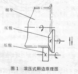
Fig. 2 is a transmission diagram of a horizontal drum double-ended flanging machine. The main working part of the machine is two actively rotating press rolls, so it is a roll type roll-over machine with passive rotation. The structure of this machine is bilaterally symmetrical. When both sides of the machine are working at the same time, both sides of the barrel are turned at the same time. However, in order to express clearly, the upper and lower parts of the figure are expressed as the upper position of the upper press and the barrel is fed. The upper left half shows the state in which the barrel of the upper press is fed to the end of the barrel in the lowest position. The following describes the working principle and process of this special plane from the two movements that the hydraulic flanges should have.
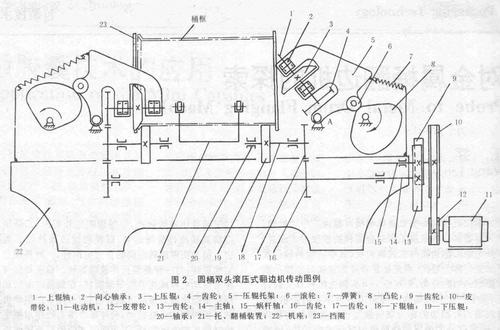
1) Feed motion: The feed motion of the machine is achieved by swinging the upper press roll 3 . The upper pressure roller 3 is fixed to the upper pressure roller shaft 1, and the upper pressure roller shaft 1 is supported by the roller bracket 5 via the bearing 2. When the cam 8 is rotated clockwise to increase the lift of the cam, the roller bracket 6 pivots counterclockwise about the fulcrum A via the roller 6 . Then, the upper press set 3 mounted on the press roller carriage is then swung into the tub until the upper press roller shaft 1 is in a horizontal position (as shown in the upper left half of the drawing) to complete the feed. Then, the cam 8 is turned to the minimum lift, the role of the Spring 7, the pressure roller bracket 5 swings clockwise back to the original position, the upper pressure roller 3 exits the barrel, then the barrel frame that has been turned over can be taken out, The next barrel to be turned can be placed.
The cam 8 is driven by a motor 11 which rotates the worm shaft 15 through a belt drive (pulleys 12 and 10), since the worm wheel (not shown) that meshes with the worm is coaxial with the cam 8, the worm shaft 15 The rotation will cause the cam 8 to rotate slowly.
2) Main Rotary Motion: The main rotational motion is expressed in the machine as the rotation of the upper, lower, and pressure rollers. This rotation is also driven by the motor 11 . The motor 11 rotates the worm shaft 15. Since the right end of the worm shaft 15 is fixed with the click wheel 9, the spindle 14 is rotated by the engagement of the click wheel 9 with the gear 13. By the engagement of the gears 16 and 17, the lower shaft 18 is rotated, so that the lower roller 19 fixed to the lower roller shaft achieves the main rotational movement. When the upper press roller swings downward, the gears 4 and 17 gradually mesh with each other, so that the upper press roller also gains the main rotary motion. At this time, the barrel located between the upper and lower press rolls is subjected to the frictional force and is driven by the press roll to rotate around its own axis, and at the same time, the flanging is completed under the feeding action of the upper press roll.
During the flanging process, the retaining ring 23 plays a role of preventing the axial movement of the barrel, and the lower end of the retaining ring 23 must be opened so as not to interfere with the movement of the upper press.
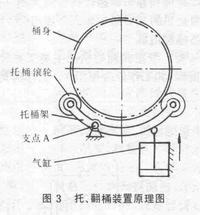
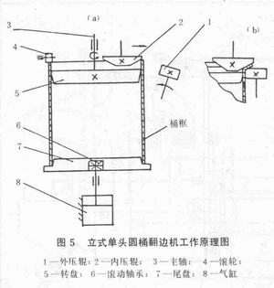
The tray and tipping device 21 supports the role of the bucket frame before the burring and functions to lift the bucket frame after the burring. Its working principle and basic structure are shown in Figure 3. In the figure, the bracket frame is arc-shaped, and four rollers are mounted on the frame to hold the horizontally placed barrel frame. When the piston in the cylinder is in the lowest position, the four bucket wheels support the bucket frame so that the bucket frame is in the state to be turned over. After the tumbling is over, the piston pushes up the support frame. Swing it up about its fulcrum A, and the bucket frame is pulled out of the bucket rack. Then let the piston go down and hold the drum rack back. The roller will hold the next barrel frame.
The structure of the edge-flighting machine shown in Fig. 2 is relatively simple and compact. The double-head flanging is simultaneous and the production efficiency is high, but the flanging uniformity is poor and the flanging dimensional accuracy is low.
Figure 4 shows another type of drum horizontal double-headed flanging machine. The machine is mainly composed of a bed, left and right headstocks, left and right flanged pressure rollers, upper pressure rollers, left and right eccentric pressure plates, lower pressure rollers and pneumatic devices. The left and right structure of this equipment is exactly the same and symmetrically arranged, which can realize the simultaneous flanging of the barrel ends. It can be combined with other equipment to form a production line for automatic production. It can also be used for manual and semi-automatic production. The following is a description of the working principle of this special machine and the operation of the single process to operate the machine by using the two movements of the drum roll-type flanging machine, that is, the main rotation movement and the feeding movement of the extra head box outside the feed movement. process.
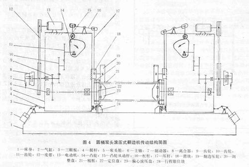
a. Feeding movement of the headstock: First, the device is connected to the power, press the left and right motor start button, and then the left and right fast-forward buttons are pressed after the feeding device comes in. The pistons in the left and right cylinders 2 are up, through the three. The eye plate 3 and the horizontal tappet mechanism 4 allow the left and right headstocks 1 to be fed, and the stroke limiting block 24 restricts the delivery process of the left and right headstocks. The barrel body, that is, the barrel frame 21 is now set on the eccentric roll. Pressure plate 23 on.
b. Main rotation movement and feed movement Press the left and right clutch close button, and the left and right clutches 8 close. At this time, the power transmitted from the motor 13 through the primary belt drive 12 passes through the gear transmission 9 to make the spindle 6 rotation; the other one rotates the cam 14 through the secondary gear drive 10, 11, the rotation of the cam then drives the flange fixed on the slider via the cam follower rod 15 and the lever 16, the press rod 17, and the slider 18. The pressure wheel 19 presses down the barrel frame, and the barrel frame moves downward along with the eccentric hydraulic disk. At the same time, due to the frictional force, the barrel frame and the flanged pressure wheel rotate together with the eccentric hydraulic disk 23 to complete the flange. After the flanging is completed, the flanging roller retreats. The eccentric hydraulic disk and the barrel frame move along with the flanging pressure wheel and return to the home position, ie, the center position, due to the spring restoring force installed in the eccentric hydraulic disk. Then, when the left and right clutch release buttons are pressed, the left and right clutches 8 are disengaged, and the left and right brakes 7 brake the rotation of the first stage gear transmission shaft so that the main shaft 6 and the flange pressure roller 19 stop moving. Finally, press the left and right rewind buttons. The piston in the cylinder 2 descends and the left and right head boxes return to their original positions. The conveyor device sends the barrel frame to the next process.
The device is more reasonable than the structure of the swing-type edge-flighting machine shown in FIG. 2 , and the adjustment is also relatively easy. The degree of automation is high, and the uniformity of the pull edge and the precision of the pull edge are also good, and it is widely used at present.
Stainless Steel Barbecue Grate
Barbecue wire Grill Grate is made of high quality 304 stainless steel, never rusting and durable. BBQ Wire mesh does not have any coating or chemical ingredients, making food safer.
Multi-functional Grill Cooking Grid Grate: This wire mesh is mainly used for BBQ Grill Mat for outdoor cooking, it can also be used as a cooling and baking rack. Or you can develop other uses for it.
BBQ Grate Mesh,stainless steel wire BBQ grate,BBQ Grill Metal Mesh,stainless steel BBQ grill grate
Shenzhen Lanejoy Technology Co.,LTD , https://www.injectionnut.com