Several methods of high precision positioning control realized by TD3100 frequency converter
Abstract: This paper proposes several methods for high-precision positioning control using TD3100 elevator-specific vector control inverter. The principle and application examples of the system are mainly discussed.
Keywords: distance control positioning control drive
I. Introduction
In the machining and manufacturing industries, high-precision position control is often required, which is generally solved by DC or AC servo, but at a higher cost. In response to this situation, this paper proposes an implementation scheme using the TD3100 inverter produced by Emerson Network Power Co., Ltd.
Second, the introduction of TD3100 distance control principle
TD3100 is an elevator-specific inverter developed by our company on the basis of high-performance vector inverter TD3000, which is favored by elevator manufacturers. Among them, the distance control function realizes the floor distance self-learning and direct high-precision docking function. The user does not need to calculate the deceleration point, which simplifies the user's software design workload, and has been widely used in elevators and stereo warehouses. The inverter learns the height information of each floor through the encoder in the memory. During the running process, if it is the given floor distance control, the inverter will automatically calculate the deceleration point deceleration stop. When the destination floor information is valid through the floor enable terminal FLE, it is acquired from the F1~F6 terminals. If it is the distance control of the given REQ request signal, the inverter will automatically calculate the deceleration point of each layer, which can be output to the controller in advance through the Y1~Y4 programmable output terminals. After receiving the deceleration signal of each layer, the controller will receive the deceleration signal of each layer. If parking is required, the parking request signal REQ is given to the inverter, and the inverter will decelerate normally according to the deceleration curve. The timing of the two distance controls is shown in Figure 1.
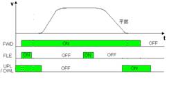
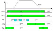
(a) Distance control for a given destination floor (b) Distance control for a given parking request
Figure 1 TD3100 inverter distance control timing
Third, using TD3100 to achieve two-point distance fixed positioning control method
For the fixed positioning control of two points, it is equivalent to the case that the elevator has only two floors. It is necessary to install the limit switch at two end points, as long as the distance self-learning between the two points is directly controlled according to the distance of the given parking request.
1, self-learning
The self-learning connection line is shown in Figure 2(a). Short the UPL and DWL, the left limit and the right limit are connected in parallel, and input to the UPL and DWL as the leveling signal. The position starting from the learning should start from the position outside the limit of the left or the right end. The position of the bit can be self-learned, and the positional accuracy can be ensured by adjusting the flat layer distance adjustment F4.07 or the layer height 1 F4.09 during normal operation. Set F4.00 to 2, and F4.01 is set according to the position width to automatically calculate the division factor. When self-learning, the FWD and SL terminals are closed, that is, self-learning starts. Note that after running to the limit switch action, the FWD command is removed and the learning is completed. Check the values ​​of F4.08 and F4.09 to see if they are recorded correctly. If the acceleration/deceleration time is too long or too short, it can be solved by adjusting F3.11~F3.16.
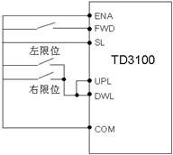
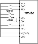
(a) Self-learning connection (b) Normal operation connection
Figure 2 Using TD3100 to achieve two-point fixed positioning control
2, normal operation
Calculate F1.07 according to Equation 1, where D is the diameter of the roller at the control line speed,  For mechanical reduction ratio. Set F5.00=15, select the X1 terminal as the distance control enable function, and adjust the S curve according to the operating efficiency required by the process. Finally, the positional accuracy of the parking can be adjusted by adjusting F3.02 and F3.21.
 (1)
(1)
According to Figure 2 (b) wiring, control FWD, REV, INS three commands, only need to control FWD / REV signal during normal operation. The INS is a jog command. When the jog is running, the INS is valid first, and then the control command FWD/REV is valid to control the jog left or right operation.
Next page
LED Lens - Ceiling Lighting Lens
Fiber Optic Sensor Lenses,plastic Laser Beam Focusing Lens,plastic Flood Light Lens
Dongguan Lianlong Photoelectric Technology Co., Ltd , https://www.lianlonggd.com