Abstract 1. The cylinder block is the main bearing for all the parts. The common point of the cylinder structure is an approximate hexahedral box structure with thin walls, more processing surfaces and more holes. It is a typical box body part, mainly processed. There are cylinder bores, main bearing bores, camshaft bores, etc., there are lubricating oil passages, cooling water passages...
1, the cylinder 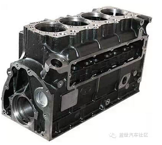
The cylinder block is the main bearing for all the parts. The common structure of the cylinder block is an approximate hexahedral box structure with thin walls, more processing surfaces and more holes. It is a typical box body part, mainly processed with cylinder holes and main Bearing holes, camshaft holes, etc., there are a variety of holes, such as lubricating oil passages, cooling water passages, mounting screw holes, etc. There are a variety of couplings, sealing bosses and facets, and their machining accuracy directly affects the assembly accuracy and work of the engine. Performance, at the same time, in order to improve the rigidity and strength of the body, there are also many reinforcing ribs.
Cylinder hole machining: processing with rough, semi-precision and fine boring. Machining of the main bearing hole: Generally, the rough machining semi-circular hole is used, and then combined with the camshaft hole and the like. Machining of the camshaft hole: generally rough, and then combined with the main bearing hole and other finishing. Machining of tappet holes: Generally, drilling, expanding (é•—) and reaming are used. The processing of the main oil passage hole: the traditional processing method is to use the twist drill for the graded feeding method, the processing quality is poor, the production efficiency is low, and the current process often uses the gun drill for processing.
2, cylinder head
The shape of the cylinder head is generally a hexahedron, which is a porous thin-walled member, which has a valve seat hole, a valve guide hole, various optical holes and threaded holes, a cam shaft hole and the like.
The plane processing of the cylinder head is generally carried out by milling with a machine-clamping gear milling cutter. The hole system is generally drilled, expanded and hinged by means of a rocker drilling machine, a combination machine, a machining center, etc.; the conduit and the valve seat are frozen or at room temperature. The loading method is press-fitted, and the displacement-pressure control method is generally used to control the assembly process in the normal temperature press-fitting process.
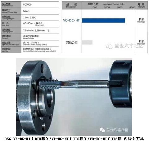
Hole machining is the difficult point of cylinder and cylinder head. The hole system is generally processed by drilling, expanding, reaming, boring and tapping. Hole machining has extremely high requirements on the tool. Any problem such as tool breakage, chipping, and poor hole accuracy will affect the machining accuracy of the hole machining. Here, Xiaobian introduces a solution for processing with OSG tools:
Hole machining case An engine plant uses OSG's VP-DC-MT (DIN standard) / VP-DC-HT (JIS standard) / VO-DC-HT (JIS standard internal cooling) series of tools, the tool has V (TICN) The coating and VP-DC-HT adopt CPM powder high-speed steel material, 0° front angle pattern to increase the blade strength, corresponding to high-speed machining, and the cutting speed is up to 30 m/min. It is used to process the hole system of the cast iron cylinder head and achieve better results.
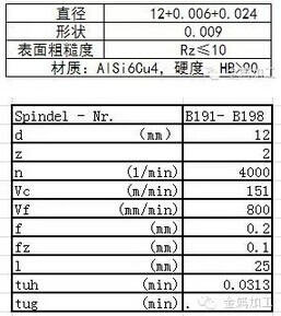
In the processing of aluminum alloy engine parts, the cutting fluid boundary lubrication performance is an important indicator to improve tool wear and control surface quality. Excellent boundary lubrication of the cutting fluid and its strong chemical adhesion can produce a pressure film between the workpiece and the tool, reduce abrasive wear, absorb cutting heat, and quickly remove the chips from the rake face of the tool, avoiding the accumulation of cutting edges. Diaphragm and bond wear. Combined with the "extreme pressure lubrication performance" mentioned above, the tool is always in a relatively ideal cutting condition, so as to achieve the effect of controlling the dimensional tolerance and improving the surface quality. Excellent edge lubrication characteristics are particularly outstanding when used for high precision machining of aluminum alloy workpieces.
Below the cutting fluid case is a practical case in which a well-known automobile manufacturer in China uses Quaker cutting fluid when machining the cylinder head tappet hole. Processing technology and processing parameters:

3. Crankshaft
The crankshaft is the central part of the automobile engine. It is subjected to repeated bending and torsional loads in the engine. Therefore, most of them are destroyed by fatigue fracture or eccentric wear and wear faster, which is an important part affecting the life of the engine. However, its shape is relatively thin and long, and it is easy to deform. The connecting rod neck and the main journal are not on the same axis, which is easy to produce imbalance during processing. Therefore, the numerical control machining of the crankshaft is compared with the machine tool equipment and the numerical control software. Strict requirements.
The crankshaft machining software case is now used in the production of crankshafts by CNC machining with a double spindle. HyperMILL® for CNC programming of any part of the crankshaft, wheelless crankshaft, turning of the connecting rod shaft, milling at the crank or multi-axis drilling at the oil hole can be easily achieved in hyperMILL®. Moreover, the crankshaft is mostly used in the trial production stage, and any rough roughing function of hyperMILL® can be processed at any angle, and the last result blank can be inherited to achieve a uniform margin. Projection finishing is the preferred choice for crank position machining. It can achieve multi-axis positioning and finishing, and the tool path is uniform and neat. The crank neck and the connecting rod neck generally need to have a margin after turning for subsequent grinding. Whether it is rough or fine, in hyperMILL®, it is only necessary to change the parameters after selecting the corresponding curve.

The center hole of the crankshaft is an important positioning reference for the crankshaft machining process. The common center hole machining method of the crankshaft is the geometric center hole and the mass center hole.
The crankshaft has high technical requirements. The journal diameter tolerance is generally IT6 tolerance, and the journal surface roughness is Ra0.4~Ra0.2μm. Therefore, in order to ensure product quality requirements, the crankshaft must be applied to all journals after rough machining. Finishing of grinding to improve journal accuracy and reduce surface roughness. The traditional grinding method of crankshaft journals is divided into two stages: semi-finishing and fine grinding. However, with the development of blank manufacturing technology and the improvement of roughing equipment processing precision, most of the crankshaft processing plants have cancelled the semi-finishing process. This can shorten the machining process of the crankshaft and reduce the production cost of the crankshaft.
For crankshaft external milling, the metalworking Xiaobian recommends a high-grade non-standard milling cutter for quick cutting and easy-to-use tools.
Crankshaft outer milling case
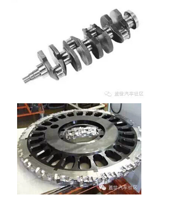
Machine tool: CNC crankshaft outer milling machine Material: 42CrMo4 HB280
Body diameter: D700mm (non-standard)
12 tool holders 168 blades (3 types)
Blade: SNHW1204XXEN8-MD07
LNHW150343TN4-MD15
LNHW1204S30EN8-MD07
Cutting parameters:
Vc=154 m/min
Vf=230mm
Ap=2-5mm
Ae=39.8mm
Blade life: 150 minutes / edge
The oil hole of the crankshaft generally has a small hole diameter and a deep depth. It is a deep hole machining, so it is difficult to process. The crankshaft oil hole machining has been gradually processed by gun drilling. The depth of the drill hole used to machine deep holes can generally be drilled. More than 100 times the diameter, the precision of the gun drilling process can be very high, and the high precision hole can be processed at one time depending on the material to be processed and the different cutting amount. In order to improve the strength of the crankshaft and increase the wear resistance of the surface, the crankshaft generally needs to strengthen the surface of the journal, rounded corners, etc. The commonly used strengthening processes include quenching, rolling, nitriding, etc., due to the wide range of quenching and high efficiency. The strengthening effect is good, so quenching has become the main strengthening process at present.
4, camshaft
The camshaft is an important component in the engine air distribution mechanism. During the engine working cycle, it properly controls the opening and closing time and opening and closing of the intake and exhaust valves, so that the compressed fuel mixture is fully combusted and the piston is pushed. Work and then exhaust the exhaust gases out of the combustion chamber, so it affects the engine's power, economy and emissions.
The camshaft belongs to the slender shaft type, which is poor in rigidity and easy to deform. To accurately control the timing of opening and closing of the intake and exhaust valves of the engine, the cam should have high contour accuracy, phase angle requirement, good wear resistance and overall rigidity. . Therefore, the machining of the journal and cam becomes the focus of the entire camshaft machining process, and the machining is often combined with turning, milling and grinding processes and surface strengthening (quenching, shot peening, nitriding) and other auxiliary processes.
The traditional machining process of cam journal: profiled multi-tool car → rough grinding → quenching → semi-finishing, fine grinding → polishing by moulding belt, current machining process: CNC milling machine with no external die milling machine → quenching → CNC no Grinding cams → flexible polishing cams by CBN grinding wheel.
One of the revolutionary new technologies that must be mentioned when it comes to camshafts is the assembled camshaft. Compared with the traditional integral camshaft, it has the advantages of light weight, low processing cost and reasonable material utilization.
The assembled camshaft is optimized by matching the cam, the hollow shaft body and the supporting journal, respectively, and is separately machined and assembled by a certain connection. The cam is generally made of carbon steel or powder sintered material, and the shaft body is The hollow seamless steel pipe is adopted, and the carbon steel cam is shaped by cold and warm forging, and is subjected to high-frequency quenching or carburizing treatment. The cam can also be sintered by the powder sintering material through the precision sintering forming technology, and the aluminum alloy is used as the shaft body.
The main process flow of the assembled camshaft includes: press-fit cam → straightening → machining the center hole at both ends → axle neck → grinding journal → grinding cam → cam quenching → deburring → straightening journal → cam journal and cam polishing → Cleaning → comprehensive testing.

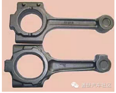
The shape of the connecting rod is irregular and complicated, and it is difficult to achieve positioning. The size of the connecting rod is a slender shaft connection, which is easy to deform; the dimensional tolerance, shape tolerance, surface roughness and the like are relatively high. The processing procedure of the connecting rod follows the principle of the first and second holes, and the other principles after the benchmark. The connecting rod is a relatively rigid part, so the positioning and clamping should reduce the influence of deformation on the machining accuracy.
The connecting rod breaking processing technology (also called connecting rod cracking) is a new manufacturing process and is gradually applied to large-scale production. The cracking of the connecting rod is a new technology for chipless fracture and splitting of the joint surface of the connecting rod and the connecting rod cover. It has the characteristics of novel concept, economical operation and remarkable benefit.
The main features of the process are:
(1) Processing of large holes. The conventional process generally involves broaching the large hole after cutting, or processing it into an elliptical shape before cutting, because it is intermittent processing, the vibration is large, the tool wears fast, and the tool consumes a large amount. The breaking process processes the large holes into a circular shape.
(2) The connecting rod body and the cover are separated. The conventional process uses a pull-off (or milling, sawing) method, and the breaking process is to break after the bolt hole is processed. After the breaking process, the connecting rod and the separating surface of the connecting rod cover are completely meshed, which improves the joint quality of the connecting surface of the connecting rod cover and the connecting rod, so the separating surface does not need to be broached and ground. Since the separating surface is completely meshed, it is not necessary to add additional precise positioning when assembling the connecting rod and the connecting rod cover, such as bolt hole positioning (or positioning ring hole), as long as the two bolts are tightened, thus eliminating the bolt hole. Finishing.
(3) Processing of joint surfaces. The traditional process is to grind the joint surface after the break, and the assembly position of the link body/cover is positioned by the positioning holes of the two bolt holes and the positioning portion of the bolt, so the perpendicularity of the bolt hole and the separation surface thereof And the center distance dimension of the two bolt holes has strict requirements. The dimensional error causes residual stress to remain in the connecting rod assembly after assembly of the connecting rod and the connecting rod cover.
(4) Bolt hole processing. The assembly position of the connecting rod body/cover of the breaking process is positioned by the rising section, and the assembly position of the connecting rod body/cover of the traditional process is matched by the positioning hole of the two bolt holes and the positioning part of the bolt. To locate, so the accuracy requirements for bolt holes and bolts are very high. When the connecting rod is processed by the breaking process, the precision requirement is greatly reduced, and the two bolt holes can be processed at different times, thus creating a convenient condition for multi-variety processing. After the big hole of the connecting rod adopts the breaking process, the separating surface of the connecting rod is the most complete meshing, so there is no influence of the separation surface and the machining error of the bolt hole.
(5) Bolt assembly. Bolts are fed, mounted, and mounted on rack-mounted brackets and hydraulically driven vertical slides through bolt feeders with vibrating hoppers, separators, and feeders with conduits and nozzles. The BOSCH tightening machine is pre-tightened. When tightening to a certain set torque, loosen the bolts by means of a device with a waiting function, clean the joint surface, and finally tighten the bolts to the requirements.
Connecting rod breaking technology In the history of connecting rod processing, the invention of the breaking process has epoch-making significance. At present, the connecting rod breaking process has been widely used in China. Shanghai Volkswagen, FAW Volkswagen, Brilliance and Chery have adopted this kind of connecting rod technology, and some professional connecting rod manufacturers have begun to adopt this technology. Domestic equipment manufacturers have already produced related special equipment.
The steel ruler water level meter is the most accurate way to measure the water level. A metric or imperial scaled steel ruler attached to a probe that is mounted on a metal or plastic steel. It is usually used to measure the water level in wells, boreholes and water level pipes. It is especially suitable for the observation of groundwater level in hydropower projects or the manual inspection of dam body immersion lines of earth and rock dams. The devices are characterized by a simple, fast and reliable measurement acquisition.
Water Level Meter,Water level indicator, level meter, deep well water level meter
Xi'an Gavin Electronic Technology Co., Ltd , https://www.cngamicos.com