The connecting rod is subjected to a drastically changing dynamic load during operation, so the dimensional accuracy, shape accuracy and positional accuracy of the connecting rod are very high, and the rigidity of the connecting rod is relatively poor, which is prone to deformation, which gives the processing of the connecting rod. Brought a lot of difficulties. The center plane of the big end and the small end of the connecting rod is also relatively high in symmetry with respect to the center plane of the connecting rod shaft. In order to ensure the processing accuracy of its symmetry, some connecting rods are designed as process bosses and center holes as an auxiliary reference for processing. The connecting rod itself has low rigidity and is easy to be deformed. Therefore, when the process is arranged, the rough and finishing processes of the main faces are separated, and the effects of machining allowance, cutting force and internal stress are gradually reduced. The deformation generated in the roughing is corrected in the semi-finishing, and the deformation generated in the semi-finishing is corrected in the finishing, and finally the precision of the part is achieved.
There are five main parameters reflecting the accuracy of the connecting rod: the symmetry of the center end of the connecting rod and the center plane of the small end with respect to the center plane of the connecting rod shaft, the large and small head hole center distance dimension accuracy, and the connecting rod large and small Parallelism of the head hole, large and small head hole size accuracy, shape accuracy, verticality of the connecting rod bolt hole and the joint surface.
Taking the connecting rod of an engine as an example, the application of the machining center and the conventional equipment on the processing link will be described for a part of the processing of the connecting rod.
As shown in the figure below, the two ends of the connecting rod have been semi-finished, and the large and small head holes have pre-cast holes. Figure 1 shows the A process, the large and small head holes and the center hole are drilled; Figure 2 shows the B process, the side of the milling process and the bolt face; Figure 3 shows the C process, which is fine and small.
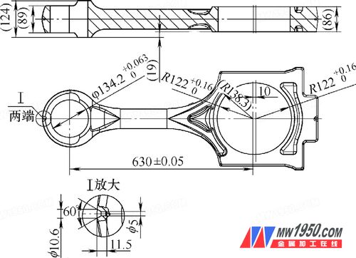
Figure 1 Rough large, small head hole and drill center hole
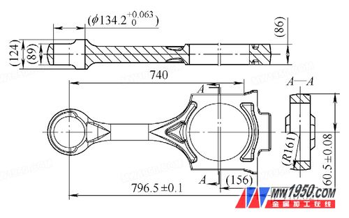
Figure 2 Milling process side and bolt face

Figure 3 fine large and small head holes
For more information, please click: Application of Longmen Machining Center in Automobile Connecting Rod Manufacturing
Stainless Steel S Trap,Stainless Steel P Trap,Wash Basin Drain Strainer,Drain Strainers & Stoppers
JIAHAOJIA SANITARY WARE INDUSTRY CO., LTD. , https://www.gagalfaucet.com