2.5 Design Simulation and Design Verification Using the 3D graphics function of the CAD system, the designer can simulate the shape of the designed product on the computer screen, and optimize the product at the beginning of design so that the product can have superior quality and minimum. The consumption and the most beautiful appearance, and before the new product is put into production, the structure, processing, assembly, decoration and dynamic characteristics of the manufacturing process can be properly analyzed and tested, thus improving the product design. Sex.
2.6 Close integration of design and manufacturing CAD design data can be used for design simulation CAE (computer-aided engineering), or can be connected with CNC machining equipment through data transmission system, and the design data can be directly used for processing of product parts and components, namely CAM. The introduction of CAD in computer-aided design can automatically complete the conversion from design to machining program [4].
3, using CAD technology for product design
3.1 Pro/E parametric design Parametric application (also called Dimension-Driven) is a topic proposed by CAD technology in practical applications. It not only enables CAD system to have interactive drawing function. It also has the function of automatic drawing. At present, it is an important subject to be further studied in the field of CAD technology application. The special product design system developed by parametric design means that designers can be freed from a large number of heavy and trivial drawing work, which can greatly improve the design speed and reduce the storage of information. The key to parametric design is the extraction and expression of geometric constraint relations, the solution of constraints and the construction of parametric geometric models. In 1988, Parametric Technology Corporation (PTC) first introduced the parametric design CAD system Pro/Engineer (Pro/E), which fully demonstrated its simple and easy advantages in the design of many common parts and components. Its main features are: feature-based, full-size constraints, full data correlation, and size-driven design modifications.
Pro/E revolutionizes traditional design concepts with a unique, parametric and part-oriented 3D solid fabrication technology, providing engineers with a revolutionary approach. Completed the conversion from 2D to 3D, realizing the CAD/CAM system. Although Pro/E has great advantages in general-purpose parts and component design, it is very difficult to complete the multi-surface product modeling directly in Pro/E. It is not impossible to complete, it takes a lot of energy and time, which increases the design cycle.
In this way, we can use PTC's industrial design software Pro/Designer (Pro/D) for surface design. Since Pro/D and Pro/E use the same database, the two are seamlessly connected and therefore designed. Medium stylists and structural engineers can work together better.
3.2 Pro/D Surface Design Capability For industrial designers and engineers who want to build surface models, Pro/D is the tool they need. Pro/D can build high quality freeform models and can be easily The conversion to other CAD systems based on manufacturing engineering.
Pro/D is able to create realistic and precise geometry, making it easier to create models and shorten design cycles. Pro/D can be used to combine visual aesthetics with engineering requirements in the mold manufacturing process, which is especially noticeable in the creation of free-form models.
3.3 Data Transfer between Pro/D and Pro/E There are two ways to exchange data between Pro/Designer and Pro/Engineer: one is to exchange data directly with Pro/Engineer, and the other is to file with Pro/Engineer exchanges data.
3.3.1 Direct Data Exchange with Pro/E If both software are running on the same machine, a direct transfer method can be used. The direct transfer method is faster and more adaptable to composite transmission. In a Pro/Designer process, you can call a part or component from the current Pro/Engineer process, or you can pass the data in Pro/Designer directly to Pro/Engineer as a CDRSIn feature, each time you send a request. The respective geometry is automatically updated in both software.
3.3.2 Exchanging Data with Pro/E in File Mode If the two softwares are not running on the same machine, you can use the file transfer method to transfer and update the data. In general, it is output as an intermediate conversion file such as IGES in Pro/Designer, and then the conversion file is opened in Pro/Engineer.
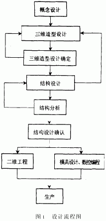
3.4 CAD application of complex design 3D design is very decorative, especially for products with complex curved surfaces. It can be combined with Pro/D and Pro/E. The stylist makes ID and surface in Pro/D. Module, start Pro/E directly from Pro/D, and lead the data to Pro/E. The structural design is done by the structural designer. Even the structural design is completed in the whole design process, due to the customer's requirements or the designer's plan. Partial changes are required. At this time, it is only necessary to change it in Pro/D. After the change is made, the original name is sent to Pro/E, then Pro/E is also changed, and the structure is not redone (of course, the structure is modified. There is a condition that there is no problem with its parent feature). The specific design process is shown in Figure 1.

Previous page next page
DSPOF is the biggest manufacturer of raw fibre for lighting in the China. Our manufacturing team have years of experience in building, randomising and polishing. This means you can be sure that you are purchasing a top quality product.
There are two general types of harnesses available - end lit or side emitting types.
Harnesses comprise one or more tails (or cables) of fibre optics which transmit the light from the light source over a distance.
Fiber Optic Light Kit,Fiber Optic Led,Led Optical Fiber,Fibre Optic Lighting Kits
Jiangxi Daishing POF Co.,Ltd , https://www.jxopticfibrelight.com